How Does 3D Scanning Work? A Beginner’s Guide to the Technology
You have a part on the bench and no drawing for it. Or you have the drawing, and now you

If you have ever searched for a way to turn a physical object into a digital model, you have probably run into two terms used almost interchangeably: photogrammetry and 3D scanning. They produce similar-looking results (a textured mesh you can rotate on screen), but they work in fundamentally different ways, and the gap between them shows up the moment you try to measure something. Understanding photogrammetry vs. 3D scanning is the difference between a model that looks right and a model you can actually inspect against a drawing.
This article explains how each technology captures geometry, why their accuracy differs by two to three orders of magnitude, where photogrammetry is genuinely good enough, and where you need a true metrology-grade scanner. We will also cover hybrid workflows that use both, so you can match the method to the tolerance your application demands.
Both photogrammetry and structured-light or laser 3D scanning end up producing a point cloud or polygon mesh that represents a real object’s surface. Both can carry color. Both can feed downstream work like reverse engineering, 3D printing, or visualization. Because the outputs look alike in a viewer, buyers frequently assume the technologies are interchangeable and that price is the only meaningful difference. It is not.
The core distinction is where the dimensional truth comes from. Photogrammetry infers 3D shape from a set of ordinary 2D photographs by solving for camera positions and triangulating common points. A professional 3D scanner measures the surface directly using calibrated optics and a known light source, so every point carries a traceable distance. One is a clever reconstruction from images; the other is a measurement instrument. That difference governs accuracy, repeatability, scale, and how much you can trust the data when a tolerance is on the line.
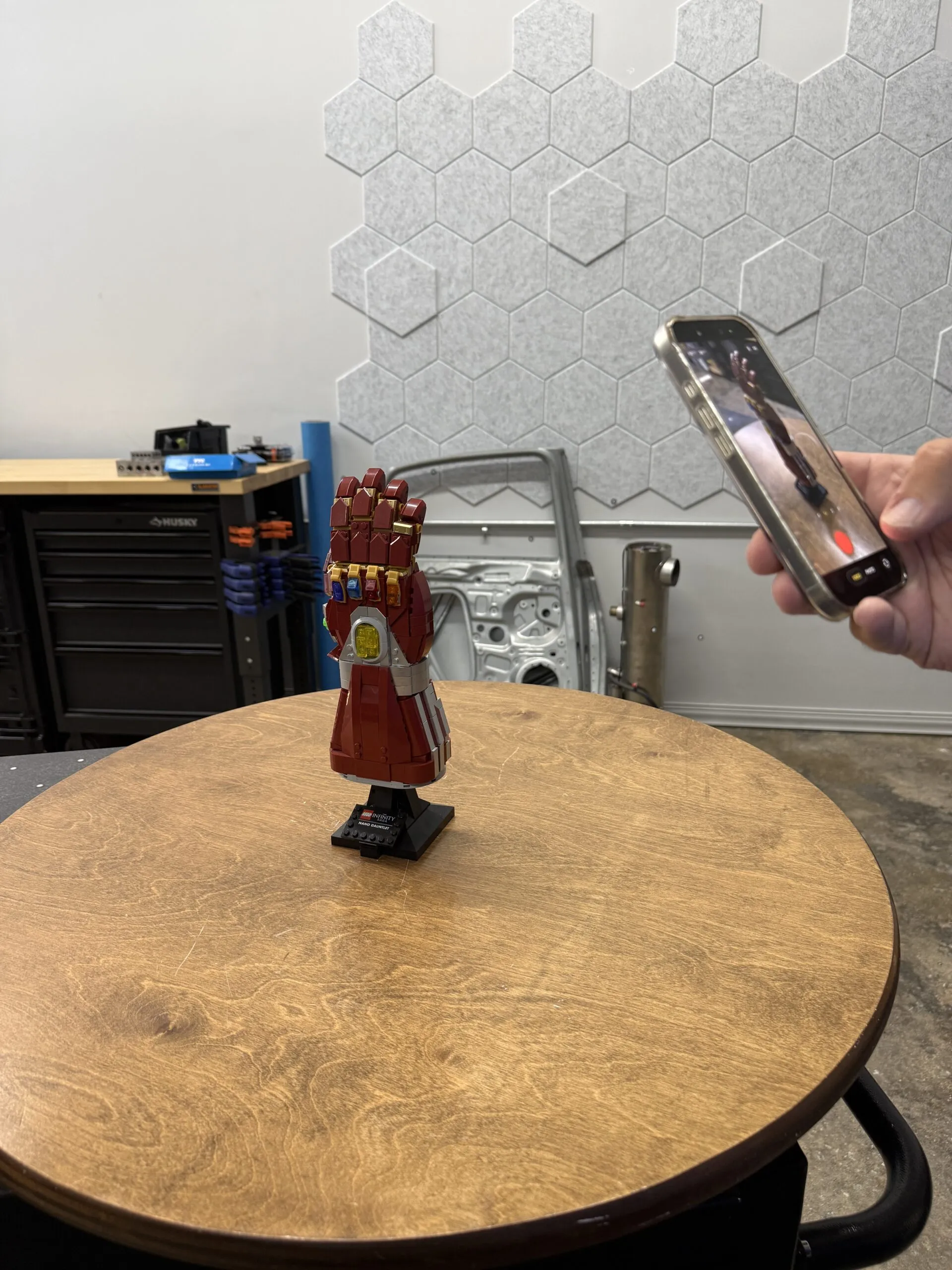
Photogrammetry is, at heart, software that turns photographs into geometry. You do not need specialized hardware to start: a decent camera or even a phone, plus reconstruction software, is enough to generate a model. That accessibility is exactly why it is so popular, and why it is so often misunderstood.
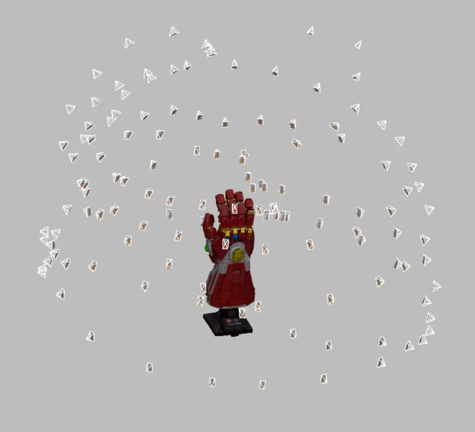
You capture an object by walking around it and taking many overlapping photos, typically dozens to hundreds, making sure each part of the surface appears in several images from different angles. The software then looks for features: distinctive pixel patterns like corners, speckles, printed text, or surface texture that it can recognize across multiple photos.
By matching the same feature in different images and solving where each camera must have been, the algorithm triangulates the 3D position of every matched point. This is the same principle your eyes use for depth perception, scaled up to many viewpoints. The pipeline generally runs in stages:
The quality of every stage depends on having enough good features to match. Crisp lighting, sharp focus, and a richly textured surface make photogrammetry shine. Poor lighting, blur, reflections, or a blank surface starve the matcher and the reconstruction degrades or fails outright.
Here is the limitation that surprises most newcomers: photogrammetry alone does not know how big anything is. Structure from motion recovers shape and relative proportions perfectly well, but it solves the scene only up to an unknown scale factor. The math that reconstructs a coffee mug from photos is identical to the math that would reconstruct a grain silo of the same shape. Nothing in the images themselves fixes the absolute size.
To put real-world units on a photogrammetry model, you must introduce a known reference: a scale bar, coded targets at calibrated distances, or a measured dimension you can type in. Get that reference slightly wrong, place it poorly, or skip it, and every measurement you take from the model is off by that same percentage. Even with a good scale bar, errors accumulate across large or feature-poor scenes, and the absolute accuracy you achieve is highly dependent on operator technique, camera quality, and capture discipline. This is the heart of photogrammetry vs. 3D scanning: scale and metric accuracy are something you have to supply and defend, not something the system guarantees.
Professional 3D scanning takes the opposite approach. Instead of inferring geometry from passive images, the scanner actively measures the distance to the surface using a controlled light source and a precisely calibrated optical system. The instrument is built and certified to produce dimensionally correct data straight out of the box.
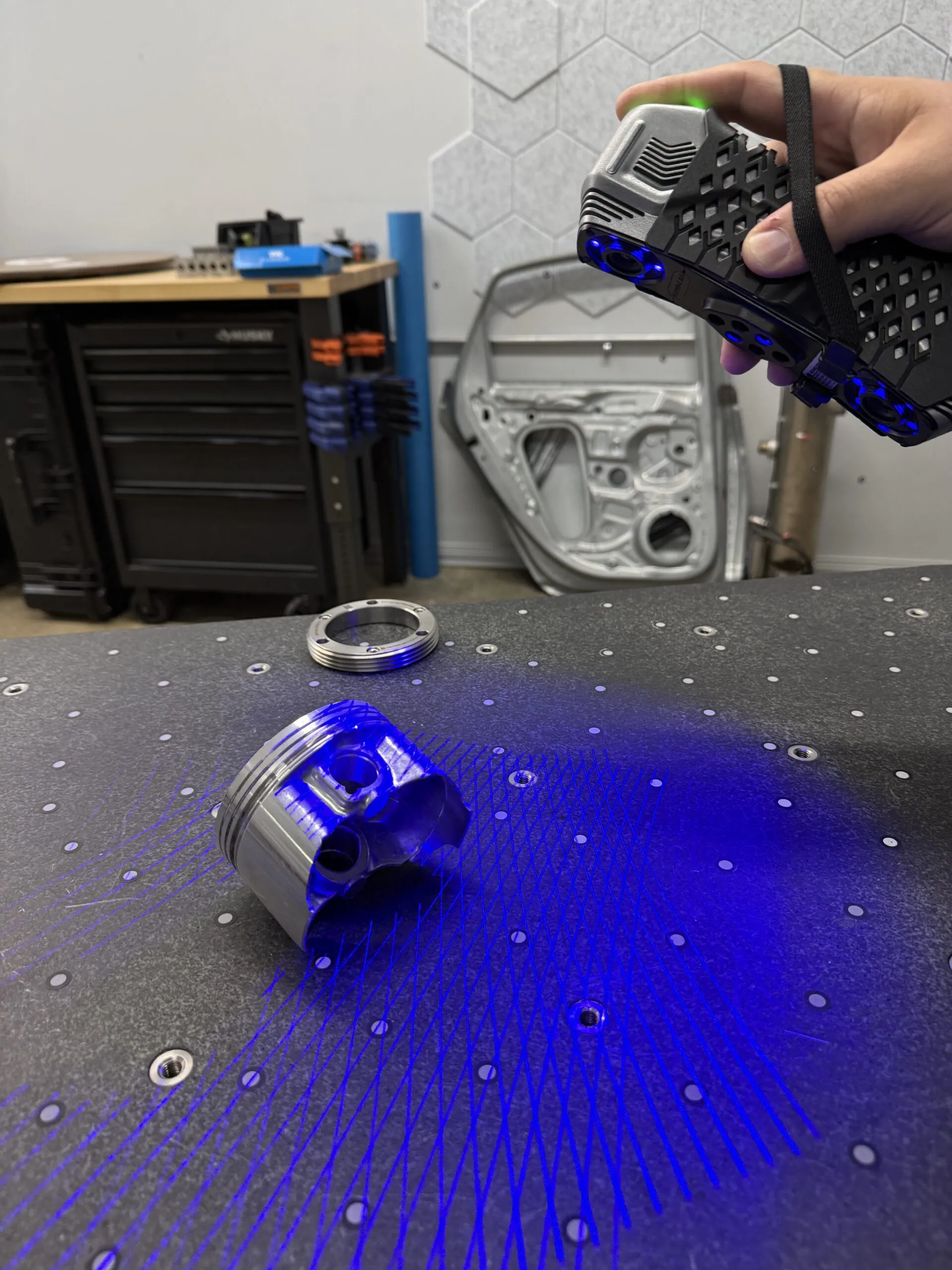
Most modern optical scanners, including the structured-light and laser systems we work with, project light onto the part and watch how it deforms across the surface. A structured-light scanner projects a sequence of patterns (often blue LED fringes) and uses the distortion of those patterns, viewed by calibrated cameras at a known baseline, to compute surface points. A laser scanner sweeps one or more laser lines across the part and triangulates the reflection. Because the device supplies its own light, it does not depend on the part having usable texture, and it works in controlled lighting rather than fighting it.
This is the key behavioral difference from photogrammetry. A passive photogrammetry rig is helpless on a blank, uniform surface because there is nothing to match. An active scanner creates its own features, the projected pattern or laser line, so a smooth, single-color surface is no obstacle to capturing geometry. The handheld and industrial systems on our portable 3D scanner and industrial 3D scanner pages all use active projection for exactly this reason.
Because the optics, baseline, and projector are factory-calibrated and traceable, a professional scanner delivers true metric data without an external scale reference. When a specification states a 3D accuracy of, say, 0.02 mm or a volumetric accuracy verified to a standard like VDI/VDE 2634, that figure is certified by the manufacturer and re-verified through calibration artifacts. You are buying a measurement instrument, not just a capture device.
That traceability is what makes scan data admissible for quality work. It is why our metrology and 3D inspection services rely on calibrated hardware paired with software like Geomagic Control X or PolyWorks|Inspector. The dimensions coming off the scanner can be trusted against a CAD model and a tolerance callout. A portable measuring arm such as the Scanology AccuArm extends that same traceable accuracy to probing and large-part inspection.
The two technologies are not competitors so much as different tools, but a direct comparison makes the trade-offs concrete. The table below summarizes where each one stands; the sections that follow explain the most important rows.
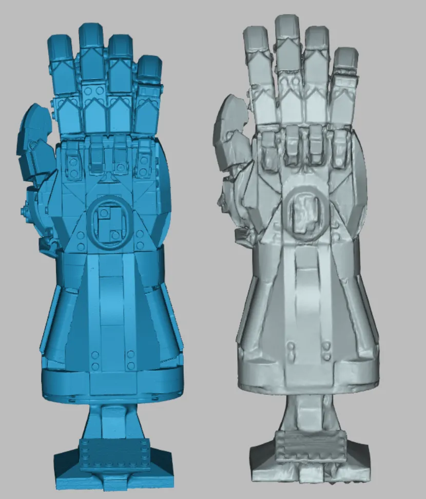
Factor Photogrammetry Professional 3D scanning Typical accuracy Tenths of a millimeter to several millimeters; highly operator-dependent ~0.02–0.1 mm, factory-calibrated and traceable Scale reference Must be supplied (scale bar, coded targets) Built in; no external reference needed Hardware cost A camera you may already own Professional system investment Software Free to mid-range reconstruction tools Metrology-grade capture and inspection suites Texture and color Excellent: full photographic detail Good to excellent, depending on the system Blank / shiny / dark surfaces Struggles or fails Handles well (may need scanning spray) Repeatability Variable shot to shot High and verifiable Best fit Visualization, large scenes, heritage, context Inspection, reverse engineering, tight tolerancesThis is the headline difference. A well-executed photogrammetry capture of a textured object might land within a few tenths of a millimeter relative to its size, but that result is not guaranteed and degrades quickly with poor technique, large scenes, or imperfect scale references. In practice, photogrammetry error is often best expressed as a fraction of object size rather than an absolute figure, and the absolute number can climb into multiple millimeters.
A professional structured-light or laser scanner, by contrast, holds accuracy in the range of roughly 0.02 to 0.1 mm regardless of how textured the part is, and that figure is calibration-traceable. For anything involving a drawing tolerance, a mating part, or a GD&T callout, that two-to-three-orders-of-magnitude difference is decisive. If you are unsure how those tolerances translate into inspection requirements, our GD&T basics training connects the dots between the print and the measurement.
Photogrammetry’s biggest advantage is its low barrier to entry. The capture device can be a camera you already own, and reconstruction software ranges from free to modestly priced. For occasional visualization work or a one-off model, that economics is hard to beat.
Professional scanning is a capital investment: you are paying for calibrated optics, certified accuracy, and software built for measurement. The right way to frame the cost is by the value of being wrong. If a dimensional error means a scrapped batch, a failed inspection, or a part that will not assemble, the price of a guaranteed measurement is trivial against the cost of trusting an uncertified one. Many teams also access that accuracy without buying hardware by using our 3D scanning services on a project basis.
Photogrammetry deserves real credit here. Because it starts from full-resolution photographs, it captures surface color and fine visual texture better than many scanners, and it does so cheaply across large scenes. For applications where photorealistic appearance matters more than dimensional precision (digital archiving of artifacts, terrain and site context, marketing visuals, game and film assets), photogrammetry frequently produces a more convincing result than a metrology scanner whose color channel is secondary to its geometry.
It is worth noting that many professional handheld scanners now capture full-color texture too, so the gap has narrowed. But if visual fidelity over a broad area is the entire goal and you do not need certified dimensions, photogrammetry remains a strong, economical choice.
The flip side of relying on photographic features is that photogrammetry collapses when there are none to find. A freshly machined aluminum block, a glossy injection-molded housing, a black rubber seal, a clear lens: these surfaces give the feature matcher nothing to lock onto, and the reconstruction comes back warped, holey, or empty.
Active scanners handle these cases far better because they supply their own features through projected light. Where reflectivity or transparency still interferes, a temporary matting coat from a vanishing scanning spray like AESUB Blue solves it cleanly and sublimates away without residue. There is no equivalent rescue for photogrammetry on a truly featureless part. The information simply is not in the photographs.
None of this makes photogrammetry a bad technology. It is the right tool for a specific set of jobs, and forcing a metrology scanner onto those jobs would be overkill. Reach for photogrammetry when the goal is appearance or context rather than certified dimensions, and when the subject plays to its strengths.
If your tolerance is “looks like the real thing” rather than a number on a drawing, photogrammetry done carefully will serve you well and save money.
The moment a dimension carries a tolerance, the conversation changes. Anything that feeds quality, engineering, or manufacturing decisions needs measurement you can defend, and that means a calibrated scanner rather than an inferred model. Choose true 3D scanning when:
In short, when being wrong has a cost, treat capture as a measurement and use an instrument designed for it. A wireless handheld like the Artec Leo or a high-resolution system for small parts such as the Artec Spider II turns scanning into a fast, traceable step in your quality workflow.
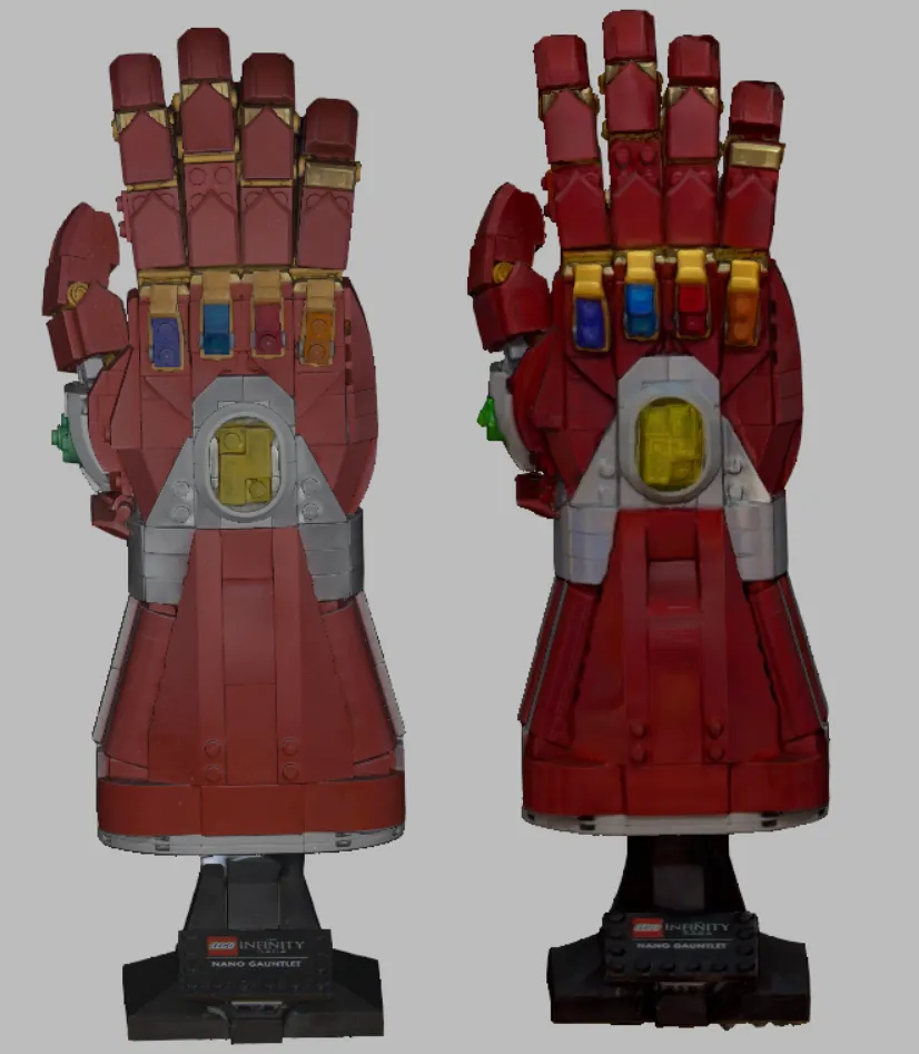
The technologies are not mutually exclusive, and some of the strongest workflows use them together. A common pattern is to scan the critical features of a part with a calibrated scanner for dimensional accuracy, then use photogrammetry to capture broad surface color or to extend coverage across a large surrounding area where high precision is not required. The scan provides the metric backbone; the photographs add appearance and reach.
Photogrammetry can also help with the scale and registration of large assemblies. Photogrammetric reference points distributed across a big object give an active scanner a stable, accurate global framework to register many individual scans into, controlling the error buildup that otherwise plagues large-area capture. The result is the best of both: photographic detail and wide coverage, anchored to scanner-grade geometry where it counts. Choosing the right mix for a given part is exactly the kind of trade-off our engineers help customers think through every day.
Photogrammetry and 3D scanning each have a place, and the skill is matching the method to the tolerance and the application. If you need certified, traceable geometry for inspection, reverse engineering, or CAD work, photogrammetry’s variable accuracy and scale dependence will hold you back, and a professional scanner is the upgrade path. Our team can help you pick the right system from our portable and industrial scanner lines, or handle the capture for you through our 3D scanning services.
We work with manufacturing, quality, and engineering teams, including aerospace and defense customers we support, to put the right measurement technology behind every decision. Whether you want to evaluate a scanner, scope an inspection project, or talk through a hybrid workflow, contact us for a consultation or quote and we will help you find the most accurate, cost-effective path for your parts.
You have a part on the bench and no drawing for it. Or you have the drawing, and now you
A fender comes off the press and something is off. The hole pattern checks out on the CMM and every

For most of the twentieth century, a crime scene was preserved with a tape measure, a roll of film, and
Every artifact and monument is on a clock. Stone weathers, pigments fade, bronze corrodes, and a single earthquake, flood, or