How Does 3D Scanning Work? A Beginner’s Guide to the Technology
September 15, 2026
Reading Time: 11minutes
In This Article
You have a part on the bench and no drawing for it. Or you have the drawing, and now you need to prove the part that came off the line matches it. Either way you need to turn a physical object into numbers, and someone has told you a 3D scanner will do that. What nobody explains is what happens between pointing the scanner at the part and getting something you can open in SolidWorks.
That gap is where the confusion lives. 3D scanning is not one technology and it is not a button. It is a measurement process, and the quality of what comes out is decided mostly by choices you make before the scanner is switched on. This guide covers how it works, what the four main methods do differently, the workflow end to end, and where the whole thing quietly falls down.
The short version, so you are not waiting on it: a 3D scanner measures the distance from itself to thousands of points on a surface, thousands of times per second, from many angles. Software stitches those measurements into one coordinate system and converts them into a continuous surface. From there you measure it, model it, or print it. Everything below is the detail behind those steps.
What is 3D scanning? Point clouds, meshes and models
3D scanning captures the shape of a real object as digital coordinates. The scanner does not understand your part. It has no idea what a hole is, or a flange, or a datum. It knows one thing: for a given spot on the surface it can see, here is an X, Y and Z value. Repeat a few million times and you have a description of the object’s exterior.
The data passes through three distinct states on the way to being useful, and confusing them causes most of the disappointment people have with scanning.
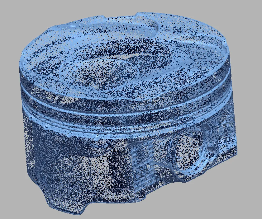
A point cloud is the raw output: an unordered bag of XYZ coordinates, sometimes with a color or intensity value attached. Points have no relationship to each other. No surface, no volume, no thickness. You can measure between points and look at it, and that is about all.
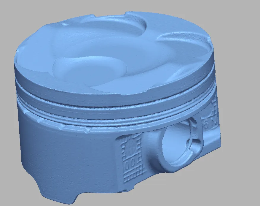
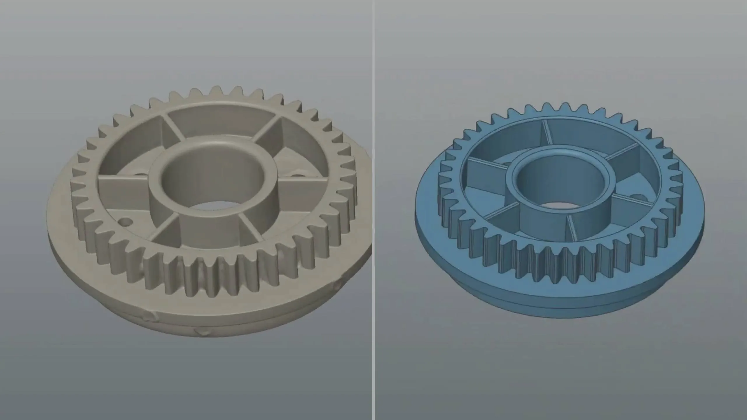
A mesh comes next. Software connects neighboring points into triangles, producing a continuous skin over the object. This is what an STL file is. If coverage was complete and the holes are filled, it has an inside and an outside. You can print a mesh, section it, measure it, or compare it to CAD.
A model is the last state, and the one people assume they are getting when they are not. A CAD model is built from features and intent: a cylinder of a defined diameter, a fillet with a radius, a pattern of holes on a bolt circle. A mesh has none of that. It is a shell of triangles that happens to be cylinder-shaped. Turning it into a parametric model is a separate job done by a person, and that job is called reverse engineering.
Point cloud What it actually is: Loose XYZ coordinates, no connectivity What you can do with it: Visualize, take point to point measurements, register scans Typical formats: PTX, E57, XYZ, ASC
Mesh What it actually is: Triangulated surface skin What you can do with it: 3D print, deviation analysis against CAD, sections, basic GD&T Typical formats: STL, OBJ, PLY
CAD model What it actually is: Features and parameters with design intent What you can do with it: Edit, redesign, manufacture, drawing creation, tooling Typical formats: STEP, IGES, SLDPRT, X_T
When a vendor says a scanner “gives you CAD,” they mean it gives you data a trained person can turn into CAD. That is not the same claim.
The core technologies: laser triangulation, structured light, photogrammetry and LiDAR
All four answer the same question, “how far is that surface from me,” in different ways, and the differences decide which belongs on your part. There is no best one, only the one matched to your part size and tolerance.
Laser triangulation
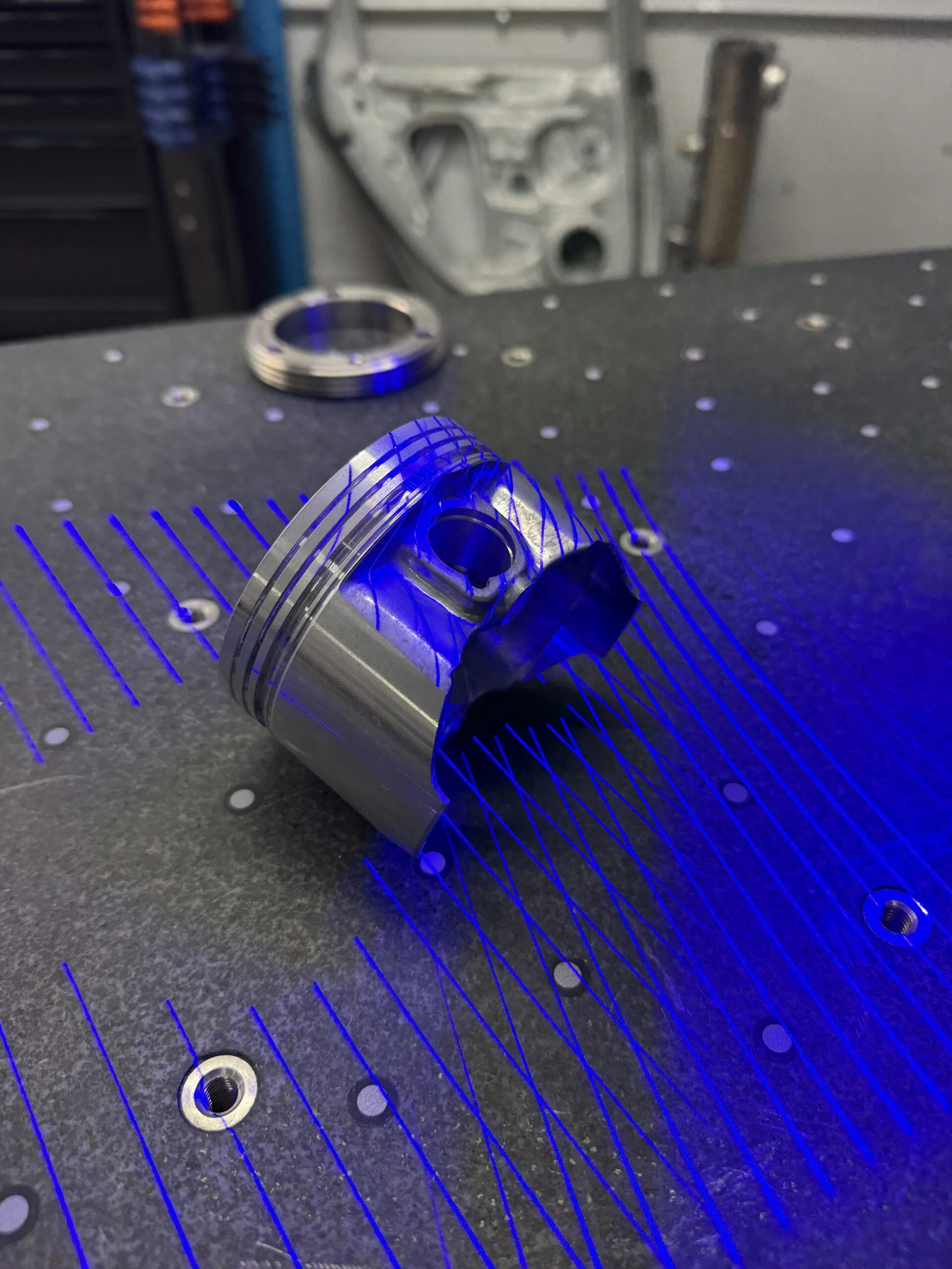
The scanner projects a laser line onto the part. A camera sitting a known distance away, at a known angle, watches where that line lands. Because the baseline between laser and camera is fixed and known, the position of the line in the image resolves into a distance through simple trigonometry. Move the line across the part and you sweep out a surface.
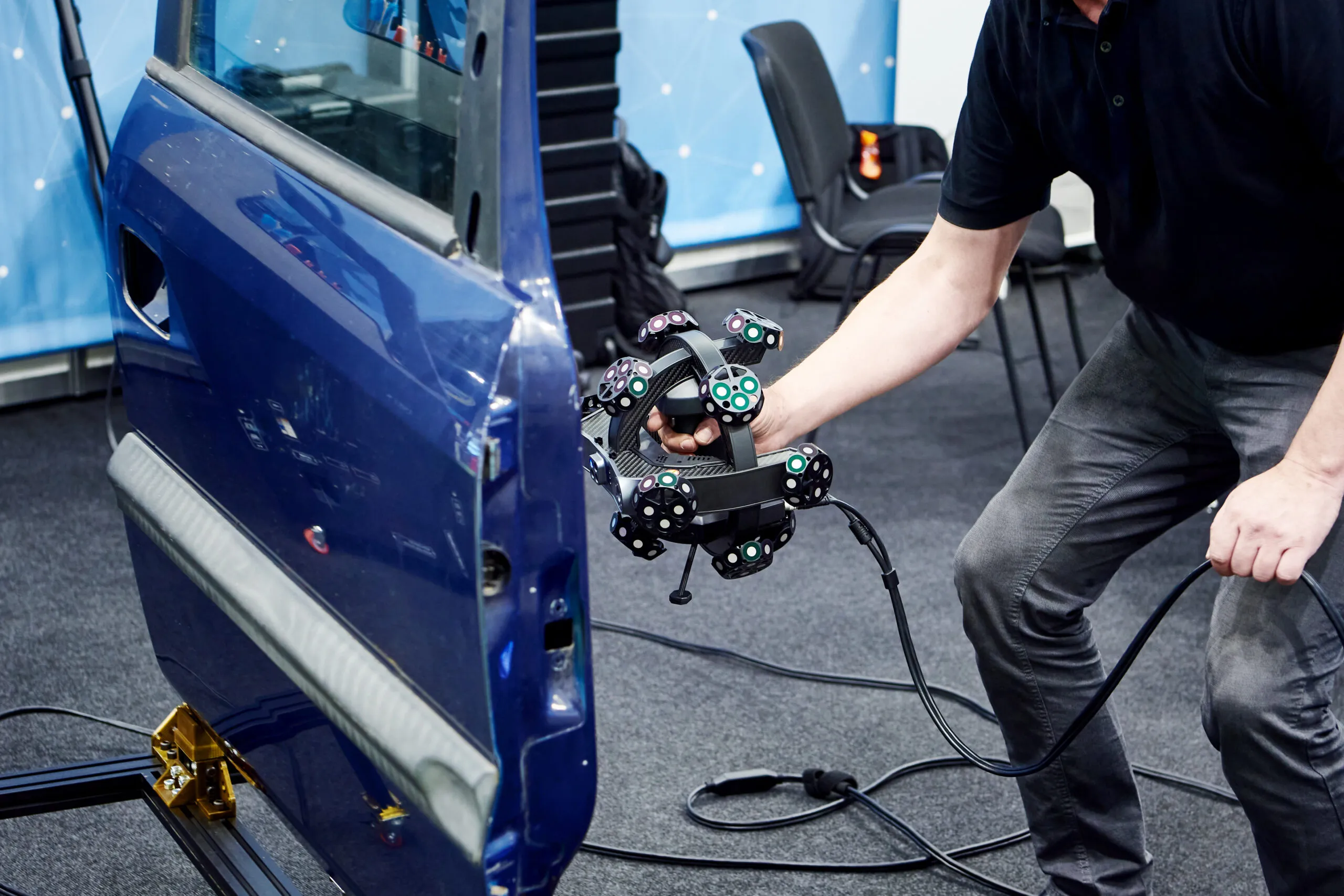
This is the workhorse for mid-size industrial parts, in handhelds and in line scanners mounted on portable CMM arms. Its practical strength is tolerance for a messy environment: it is less bothered by ambient light than pattern-based methods, and copes reasonably well with darker or slightly reflective surfaces where other systems struggle. The tradeoff is that it captures a line at a time rather than an area, so coverage depends on how patiently you move.
Structured light
Instead of a line, a structured light scanner projects a known pattern across the whole field of view: fringes, stripes, or a sequence fired in quick succession. One or two cameras watch how the pattern deforms as it drapes over the geometry. Deviation from the expected pattern resolves into depth for every pixel at once.
Capturing a whole area per exposure rather than a line makes structured light fast, dense, and excellent on organic shapes where detail matters. The tradeoffs are real. Ambient light interferes, so bright shop floors or sunlight through a roll-up door cause problems. Blue LED systems mitigate this by working in a narrow band away from most ambient noise, but do not eliminate it. Shiny and transparent surfaces remain the hard case, because the pattern needs a cooperative surface to land on.
Photogrammetry
Photogrammetry projects nothing. It takes ordinary photographs, lots of them, from many positions. Software finds features appearing in multiple images, works backwards to figure out where each camera must have been standing, and triangulates 3D positions for those shared features. It is the math your brain does with two eyes, run across hundreds of viewpoints.
The appeal is cost and reach: a camera and a drone can capture a building, a quarry, or a ship’s hull. The catch is that photogrammetry needs texture to latch onto. A blank white wall or a clean machined surface gives the algorithm nothing to match, and the reconstruction falls apart. It also has no inherent sense of scale, because a small object photographed close up looks identical to a big one far away. You establish scale with calibrated scale bars or coded targets. Skip that and you get a beautifully detailed model of the wrong size.
LiDAR and time of flight
Time of flight scanners, including most terrestrial LiDAR units, send out a pulse of light and measure how long it takes to come back. Light travels at a known speed, so time converts directly to distance. Phase shift systems compare the phase of a modulated beam instead of timing a pulse, which buys speed at shorter ranges.
This is how you capture a factory floor, a bridge, or a room full of equipment. Range is the entire point, measured in tens or hundreds of meters. What you give up is resolution, because at long range the points are farther apart and fine features disappear. LiDAR is the right tool for as-built documentation and clash detection. It is the wrong tool for checking a bore.
Laser triangulation Best working scale: Palm-sized to vehicle-sized parts Strength: Robust in real shop conditions, forgiving surfaces Where it struggles: Line at a time, slower area coverage
Structured light Best working scale: Small to medium parts Strength: Dense, fast, high detail on freeform shapes Where it struggles: Ambient light, shiny or clear surfaces
Photogrammetry Best working scale: Medium objects up to sites Strength: Low equipment cost, huge reach Where it struggles: Needs surface texture, needs external scale reference
LiDAR / time of flight Best working scale: Rooms, buildings, sites Strength: Long range, captures entire spaces quickly Where it struggles: Coarse for part-level features and tight tolerances
Plenty of jobs combine methods. Photogrammetry often builds an accurate global framework of target positions on a large object, and a handheld scanner fills in local detail against it, fixing the weakness of each method with the strength of the other. Choosing between the scanner families available is less about brand loyalty than about being honest regarding the size of the thing you are measuring and the tolerance you have to hold.
The end-to-end 3D scanning process, step by step
Here is what actually happens on a job. The scanning itself is a surprisingly small slice of it.
Define what the scan is for. This sounds like consultant filler. It is not. The required tolerance and the intended output drive every other decision: which scanner, how much prep, how dense the data, how long processing takes. A scan for a 3D printed display piece and a scan for first article inspection are not the same job, even on the same part.
Prepare the part. Clean it. Fixture it so it cannot move and, if it is compliant, so it is not sagging in a way it never would in service. Difficult surfaces get treated: a light coat of removable matting spray kills reflections, and reference targets go on when the system needs them for tracking. This is where sprays, targets and fixturing accessories earn their keep, and it is the step people skip when they are in a hurry.
Calibrate and warm up. Optical systems drift as they change temperature. Manufacturers publish a warm-up period and a calibration routine for a reason. Running a calibration artifact takes a few minutes and is the cheapest insurance in the workflow.
Scan. The operator works the part systematically, keeping the scanner inside its stated standoff range, holding a sensible angle to the surface, and building deliberate overlap between passes. Steep incidence angles produce noisy points. Rushing produces gaps you notice back at the desk, after the part has gone back to the customer.
Register and align. No single view captures a whole object, so multiple scans get pulled into one coordinate system, aligned off targets, geometry, texture, or a tracked position. This is where error accumulates. Each alignment carries a small residual, and residuals compound across a long chain, which is why long thin parts are harder than compact ones.
Clean the data. Delete the fixture, the table, the operator’s hand, the stray points floating in space, and the noise around edges. Automated filters do most of it. Judgment does the rest, because “noise” and “a real feature that looks odd” can be uncomfortably similar.
Merge and mesh. The overlapping clouds get fused into one triangulated surface. Then you decide on hole filling, smoothing and decimation, and each of those trades fidelity for tidiness. Fill a hole and you have invented geometry that was never measured. Sometimes that is fine. On an inspection job it is not.
Produce the deliverable. The mesh is raw material, not the product. What the customer wanted was a report, a model, or a printable file.
Notice how much of that is preparation and post-processing. Time with the scanner in hand is the minority of the effort, so anyone quoting scanning time alone is describing a fraction of the work.
From raw scan to usable output
Three destinations cover almost everything, and each demands different things from the same scan.
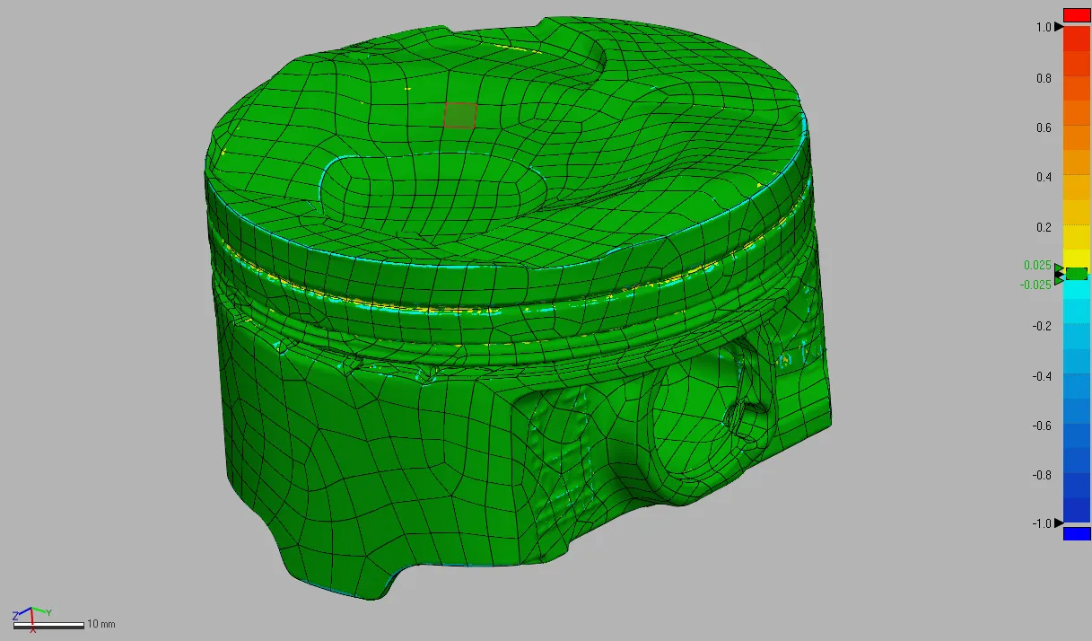
An inspection report. The mesh gets aligned to the nominal CAD, either by best fit or, more correctly, by the datum scheme on the print. That distinction matters: best fit tells you how close the shape is, while a datum alignment tells you whether the part is in tolerance as defined. Then the software produces a color deviation map and extracts the dimensions and GD&T callouts. The color map is the famous image, but the callouts are the answer. This is the heart of dimensional inspection and metrology work, and it lives or dies on the alignment, not the picture.
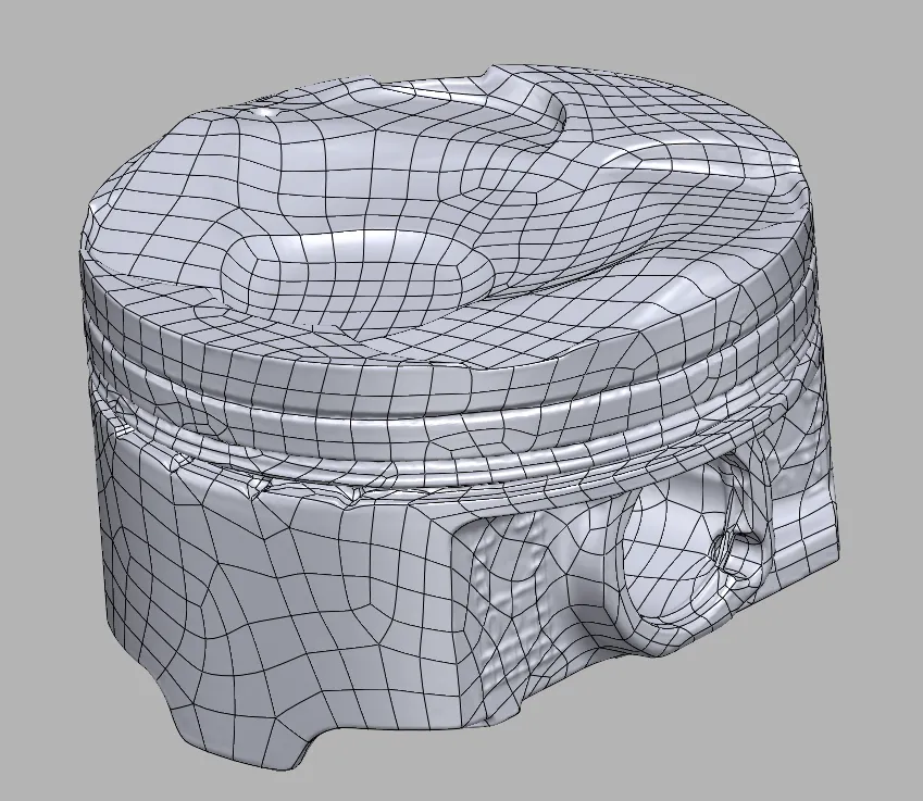
A CAD model. Two roads exist and they are not equal. Automatic surfacing drapes a NURBS patchwork over the mesh and hands you a STEP file quickly. It looks like CAD, but it is not meaningfully editable, its cylinders are not really round, and its planes are not really flat. Fine for a mold cavity of a freeform shape. The other road is a parametric rebuild, where an engineer decides which surfaces were meant to be planes and which cylinders were meant to share an axis, then reconstructs the part as clean features with real dimensions. Slower, and what you want if the model will be edited or manufactured from. Choosing between a modeled CAD deliverable and a fast auto-surface is the biggest cost lever in a reverse engineering project, and it should be decided at quoting, not halfway through.
A 3D print. The least demanding path geometrically and the most demanding about mesh hygiene. The mesh must be watertight, correctly oriented, free of self-intersections and non-manifold edges, and at a wall thickness the process can build. Scanners routinely produce meshes that look perfect on screen and fail a slicer instantly.
What 3D scanning can and cannot do
This is the section most vendor pages leave out.
It cannot see what it cannot see. Optical scanning captures line of sight surfaces. Internal cavities, blind bores, deep undercuts and anything behind anything else are not measured. Software will happily bridge the gap and give you a smooth confident surface that is entirely fictional. If internal geometry matters, you are talking about industrial CT, not optical scanning, and that is a different machine with a different budget.
Shiny, clear and very dark surfaces fight back. Polished metal, glass, black rubber and translucent plastics all interfere with the optical assumption that light lands on a surface and scatters back diffusely. Matting spray solves it, but the spray has thickness, and that thickness sits between the scanner and the real surface. On loose tolerances it is irrelevant. On tight ones it is a systematic error you have to account for.
Small features do not survive. Sharp edges get rounded. Small fillets blur. Hole edges roll over. Threads are essentially unmeasurable optically in any way you would trust. Features near the resolution limit come back soft. If the feature that matters is near that limit, do not scan it. Gage it.
Published accuracy is not shop floor accuracy. Manufacturer figures are established under controlled conditions with calibrated artifacts, stable temperature, and a well behaved surface. Your reality includes thermal drift, vibration, a part warmer than the reference standard, an operator on hour six, and a long alignment chain. Real world results are worse. Not catastrophically worse, but worse, and honest planning assumes it.
Flexible parts move. Sheet metal, gaskets, hoses, thin housings and anything long and slender deform under gravity and clamping. The scanner faithfully records the shape the part had at that moment in that orientation. Whether that is the shape it has in the assembly is a question the scanner cannot answer.
It does not replace a CMM. For a single tight tolerance feature, a touch probe still wins on accuracy and traceability. Scanning wins on whole surface coverage, freeform geometry, speed, and catching problems no one thought to specify. The honest answer for most quality departments is both, used where each is strong. Anyone telling you to replace your CMM with a scanner is selling, not advising.
It will not give you design intent. A scan tells you what the part is, not what the designer meant. Was that surface supposed to be flat, or is the slight crown intentional? Is the 9.98 mm bore a worn 10 mm bore or a deliberate 9.98? Answering that takes an engineer who understands how the part is made and what it does.
Common applications by industry
The technology spread across manufacturing because one capability, capturing real geometry fast, solves very different problems shop to shop.
In aerospace, scanning handles first article inspection of complex machined and composite structures, tooling verification, and repair assessment where the drawing is decades old and the tooling is gone. In automotive and motorsport, it drives panel gap and flush analysis, die inspection, aftermarket fitment design, and the fast physical to digital loop that prototype work depends on.
In heavy equipment and industrial maintenance, the dominant use is legacy and obsolete parts. A pump housing fails, the OEM is gone or the lead time is unacceptable, and the only master is the broken casting in front of you. That is a scan, a model, and a part. It is unglamorous work and probably the highest value application in the whole field.
In medical, dental and orthotics, scanning captures anatomy for custom devices, because bodies are not parametric and no two are alike. In consumer products, it supports fit checks against existing hardware and ergonomic work from physical mockups. In art and heritage, it documents objects that cannot be handled or risked. The specifics differ enough by sector that it is worth looking at how the technology is applied in your industry rather than assuming your neighbor’s workflow transfers to your parts.
If you are working out whether scanning fits your part, tolerance and timeline, that conversation is worth having with someone who both sells the equipment and runs it on real jobs, because those two perspectives catch different problems. Get in touch with our engineers and describe what you are trying to measure and what you need at the end. We will tell you honestly whether scanning is the right approach, and if it is not, what is.
SCHEDULE
Talk to a metrology consultant
Free 30-min scoping call to find the right scanner for your workflow.
QuickSurface AI launches November 17, 2026 as part of QuickSurface Pro 2027, turning 3D scans into editable parametric CAD models. Here is the release date, pricing, which editions include it, and the first teaser videos.