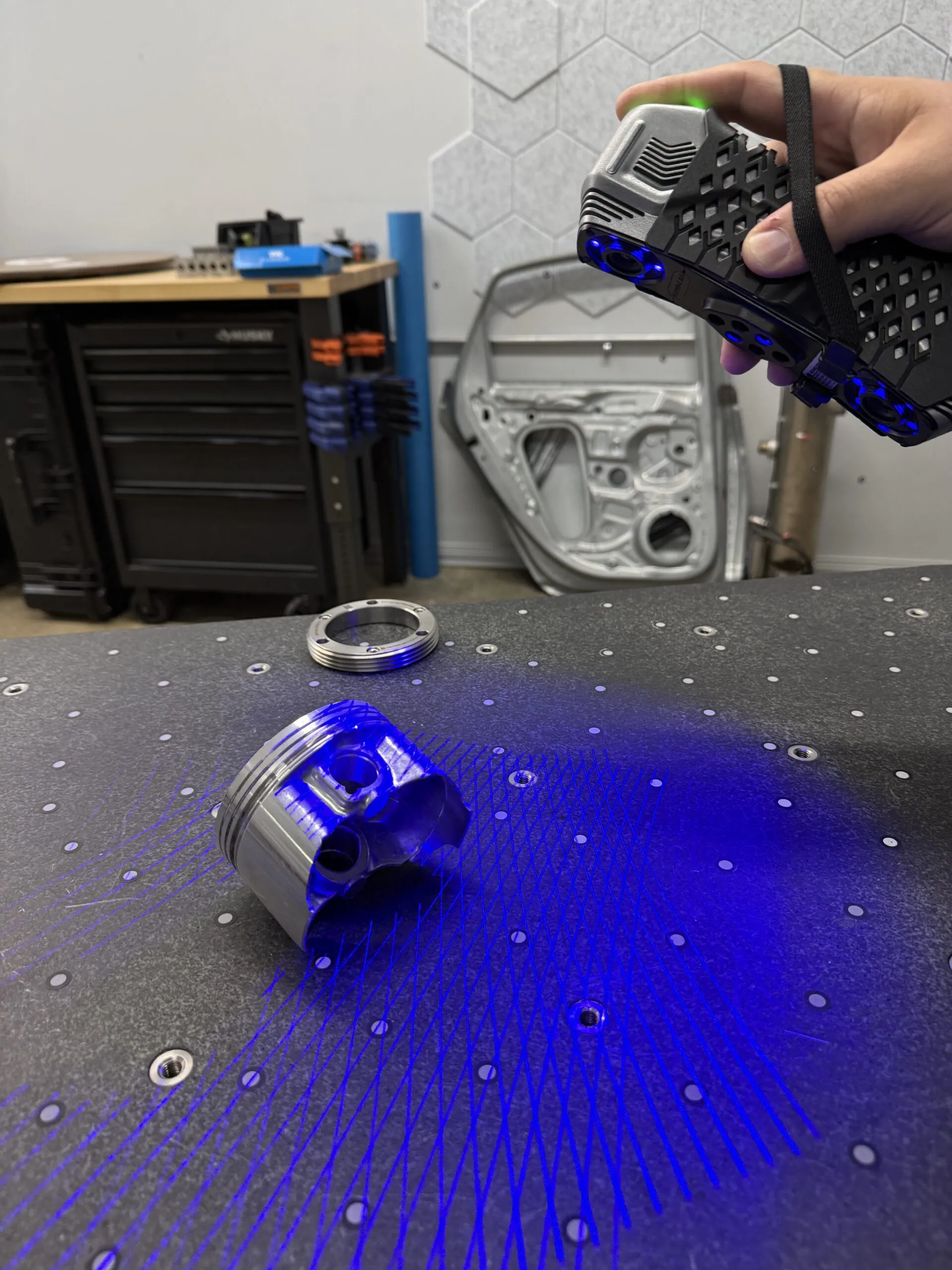
How Does 3D Scanning Work? A Beginner’s Guide to the Technology
You have a part on the bench and no drawing for it. Or you have the drawing, and now you

A fender comes off the press and something is off. The hole pattern checks out on the CMM and every dimension on the print is in tolerance, but the panel still fights you at the assembly fixture, and nobody can say exactly where. This is the moment that sells 3D scanning in automotive, and it has almost nothing to do with the scanner. It is that the CMM gave you forty points on a surface with a million places to go wrong.
Automotive parts are mostly freeform. Sheet metal springs back, plastic warps as it cools, castings shrink unevenly, and none of that shows up in a list of feature dimensions. A point cloud does not miss it, because it does not decide in advance where to look. That difference holds from the first clay buck through the last part off the line.
Three reasons, all still current.
The first is geometry. A cylinder head has prismatic features a CMM measures beautifully. A door outer panel does not. Class A surfaces are defined by curvature continuity and highlight behavior, not a stack of callouts, and you cannot inspect a highlight with a touch probe. The second is volume. When you make eight hundred parts a shift, an inspection that takes two hours per part is a bottleneck with a report attached.
The third is launch timing. Programs are scheduled backward from job one, and tooling tryout sits on the critical path. Every die that goes back to the bench for guess-and-check rework burns days the program does not have. The value of scanning during tryout is telling the toolmaker where to cut before they cut.
Clay is not a nostalgia exercise. Designers still cut clay because a full-size model tells you things a monitor will not: how a shoulder line reads at fifteen feet, whether a surface transition looks heavy in daylight. The problem is that clay lives in the physical world and the rest of the program lives in CAD. Somebody has to move it across.
That move is a digitizing job. You scan the model, build surfaces from the data, and hand engineering a math model they can work from. The catch is that a raw scan is not a deliverable. It is a mesh, and a mesh is not Class A surfacing. It reproduces every thumbprint and chatter mark the modeler left, and an engineering group will hand it right back. The work that matters is the surfacing after, which is why CAD modeling from scan data is a different skill from running the scanner and should be resourced as one.
The same loop runs in reverse for physical prototypes. You have a printed or machined part and you want to know whether it matches the CAD it came from before you spend a week testing it. Scan it, align to the model, read the deviation map. If it is out where it matters, you found out in an hour instead of after the test cell told you something confusing.
Tooling is where scanning pays for itself fastest, and the application most shops underuse. A stamping die is a hand-finished object that is supposed to match a CAD model and never quite does. Benchwork happens. Somebody blues the die, sees a high spot, grinds it, repeats. That loop works, but it is slow and undocumented, so the knowledge lives in one toolmaker’s hands and leaves when they retire.
Scanning the die gives you three things the blue does not. A deviation map of the whole surface rather than the contact patches. A record of its condition at a point in time, so you can compare it against itself six months later and see wear. And data a CAM programmer can use, which makes the correction a machining operation, not a hand one.
The springback case is the one worth understanding. Formed panels do not hold the die’s shape, they relax toward something else. Scan the panel and the die, compare both to CAD, and you can compensate the die geometry to hit the part you want. Simulation predicts this too, and it is genuinely good now, but from assumptions. The scan measures what your steel, on your press, at your lubrication, actually did.
Rework goes down for one unglamorous reason: you stop cutting twice.
The tryout loop is iterative by design: run parts, find them out, correct, run again. Each pass costs press time, material, and calendar. Most of the waste is not in the cutting. It is in the passes where the correction was aimed at the wrong place, because the diagnosis came from a handful of check points and a toolmaker’s read.
Full-field data collapses that. When you see the entire deviation field at once, the correction is aimed instead of estimated, and the number of passes drops. How far depends on your part and how disciplined the loop already was. Be suspicious of anyone who quotes a fixed percentage without seeing your process, including us.
The other half is mold maintenance. Injection molds wear, get welded and reworked, and drift from the model that spawned them. Periodically scanning a tool that runs a critical part turns drift into a measurement rather than a surprise in a customer complaint. That is routine dimensional inspection work, and it is cheap next to a tool going out of spec unnoticed.
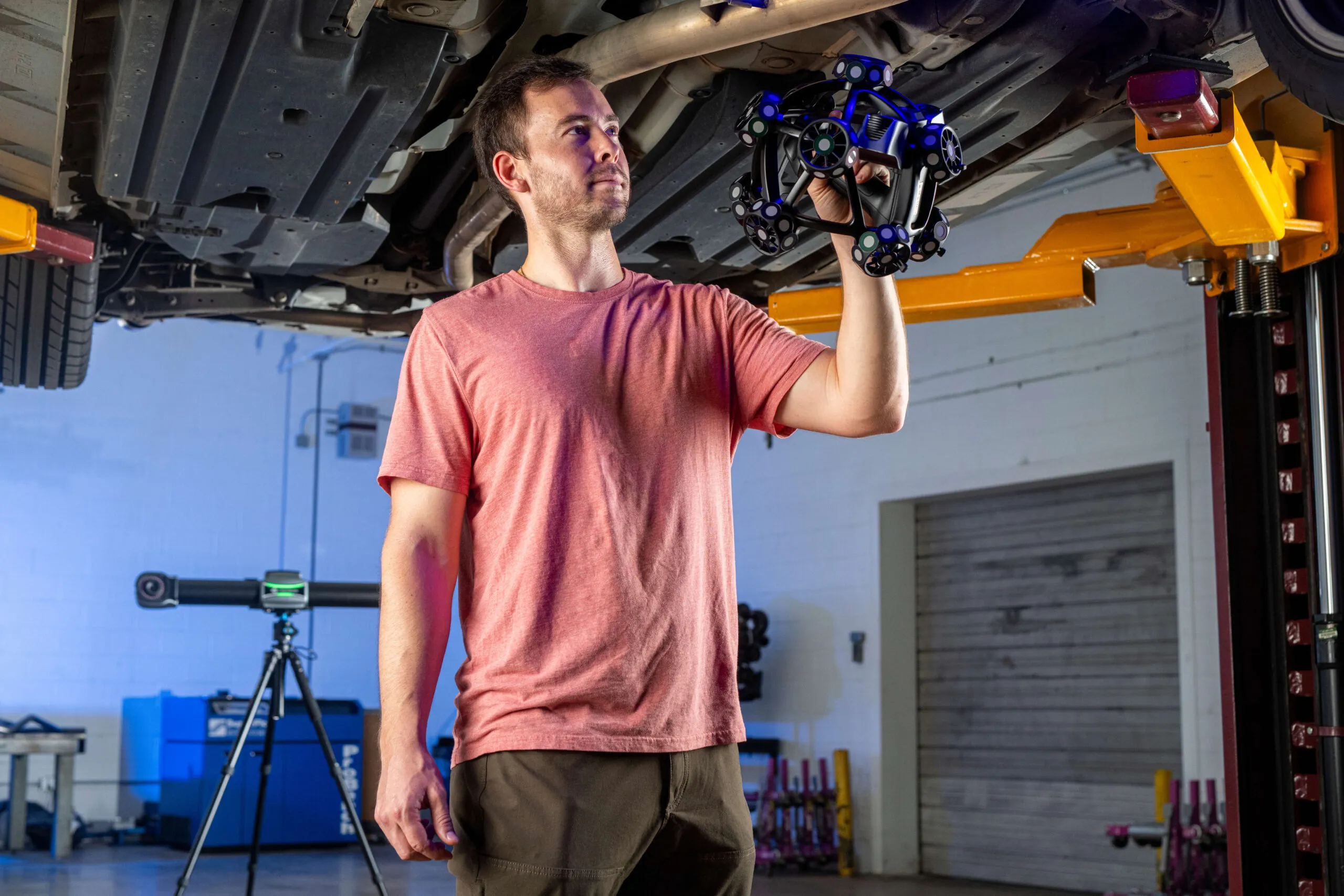
This is where automotive scanning gets genuinely difficult, and where the gap between a demo and a working installation is widest. Lab scanning is forgiving. Production is not: you have a cycle time, a part that may be warm, ambient light that changes when the bay door opens, vibration, and an operator whose actual job is something else. A system that works brilliantly in a metrology room can fail fifty feet away on the floor, and the reason is almost never the sensor.
The first question is not which scanner. It is what decision this data drives. In-line inspection nobody acts on is expense theater. If the answer is “we will stop the line,” you need speed and reliability above all. If it is “we will trend it and adjust weekly,” you can run at-line instead, and you just saved a great deal of money and pain.
Body-in-white is the classic case: a large welded assembly where the individual parts were all in tolerance and the assembly still is not. Fixtures move, weld shrinkage pulls things, and no amount of measuring incoming panels tells you what the body will do.
The practical approach is measuring at the states that matter, typically framing and then complete body, and comparing against both CAD and the assembly’s own history. What you are hunting is not a single out-of-spec hole. It is drift: a trend where one side of the body walks away from nominal over a shift, which usually means a fixture or a weld gun, not a part. You only see that if you repeat the measurement on a schedule.
Gap and flush is the metric customers actually perceive. Nobody in a showroom measures a hole position. Everybody runs a thumb down the gap between door and fender.
It is also a measurement people get wrong. Gap and flush is defined between two parts along a specified section, at a specified point, in a specified direction. Move the section slightly and the number changes. This is why handheld gauges and scanned values disagree so often: they are not measuring the same thing, and the argument that follows usually ends with somebody deciding the scanner is broken. If you are moving gap and flush to scanning, nail down section definitions first, in writing, agreed by everyone who reads the report. Then correlate. Skipping that is the most reliable way to make a good system look bad.
The aftermarket problem is the opposite of the OEM problem: no CAD, no print, and the only authority on what the part should be is a part that already exists, possibly a rusty one.
This is reverse engineering, and scanning is only the first hour of it. The scan tells you the shape of the object in front of you, including its damage and its wear. It does not tell you design intent. Deciding that a surface was meant to be a cylinder of a specific nominal diameter, and that the ovality you measured is wear rather than intent, is engineering judgment. No software does that for you, and the ones that claim to are producing a mesh with a solid model draped over it.
Restoration adds a wrinkle: you usually want the part the factory meant to make, not the part you have. A panel that has been hit, filled, and re-hit is a poor source of truth. The usual play is scanning several examples, or using symmetry and the good regions to reconstruct the compromised ones. It is slower than clients expect, so explain that before you start. Where this shines is obsolete tooling: if the die and the supplier are both gone, a good scan and a properly built solid model is the only path back to the part.
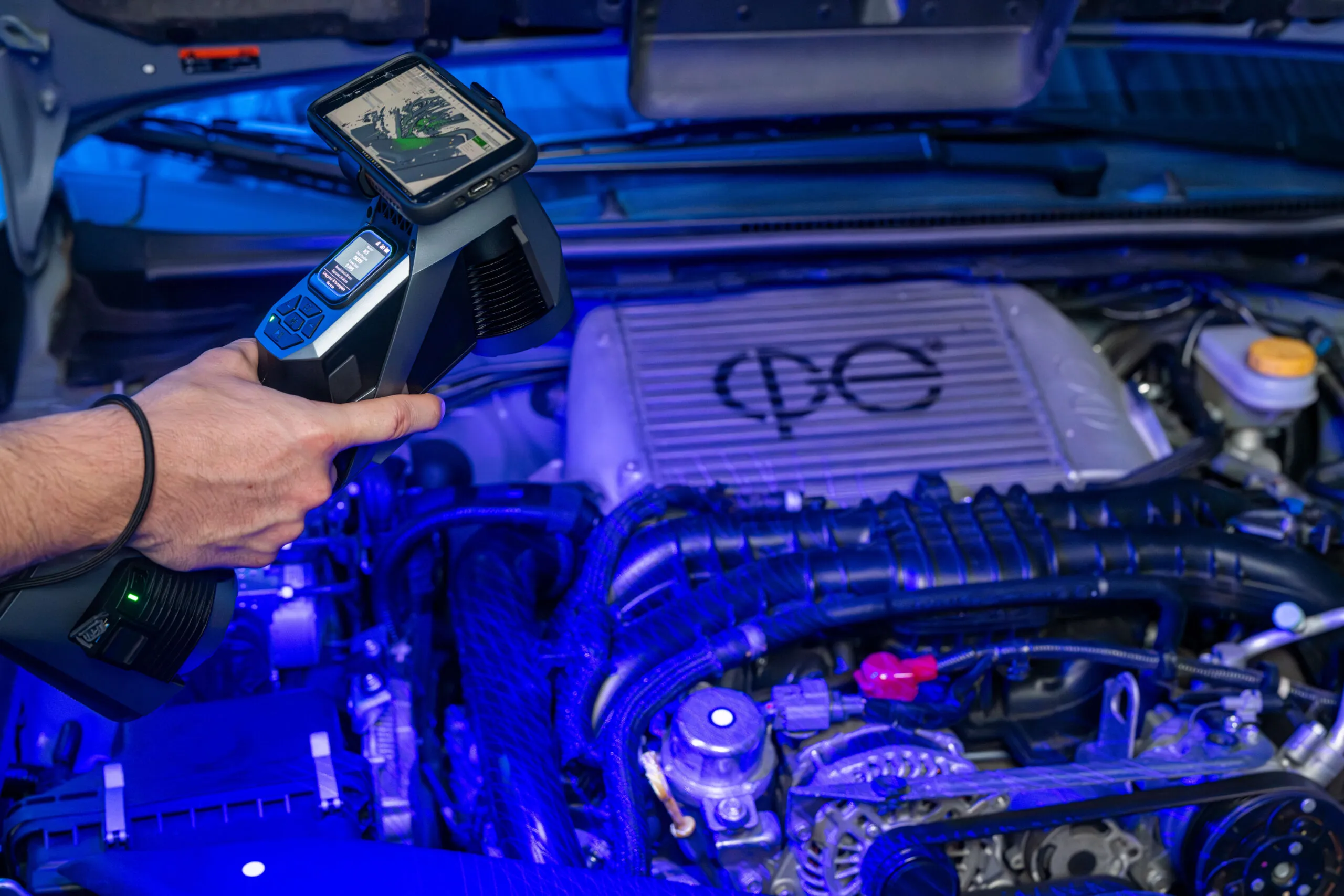
EV programs did not invent new metrology, but they changed which problems are hard.
Battery enclosures are the clearest example. An enclosure is a large, flat-ish, sealed structure whose critical characteristic is not a hole position but the flatness of a sealing surface running several meters around the perimeter. Miss it locally and you have an ingress path. A CMM sampling that flange every 50 mm can walk straight past the one region that leaks.
Large structural castings are the second. Consolidating dozens of stamped parts into one aluminum casting moves the tolerance problem from an assembly into a single component, and castings distort during cooling and heat treat in ways that are hard to predict. It is common to find a casting that looks terrible against one alignment and acceptable against another, which is a datum conversation, not a part conversation.
Thermal interfaces are the third: module stacks, cooling plate contact, busbar positioning. Area problems want area measurements. If your quality system was built around prismatic features on machined parts, EV components will find its limits quickly.
There is no automotive scanner, only scanners that fit specific problems. The most common buying error we see is a shop buying one system to do everything, then finding the thing it does worst is the thing they need daily.
Trim, interior, small assemblies
Typical fit: Handheld structured light or laser
What usually goes wrong: Underestimating surface prep on gloss and black plastic
Full vehicle, body-in-white
Typical fit: Long-range plus photogrammetry reference
What usually goes wrong: Stitching drift with no reference frame
Tooling and dies
Typical fit: Structured light on a stand or arm
What usually goes wrong: Fixturing and access, not sensor accuracy
High-volume production
Typical fit: Automated cell or robot-mounted sensor
What usually goes wrong: Integration and part presentation, not the scanner
Handheld is the workhorse. Interior parts are small enough to walk around, complex enough that fixed setups struggle, and numerous enough that setup time dominates. A good handheld gets you a complete part fast, and fast is what decides whether people use the thing at all.
The real constraint is optical, not dimensional. Automotive interiors are full of gloss black plastic, chrome, and clearcoat, the three surfaces scanners like least. Prep works, but it is a step people leave out of their time estimate and then get frustrated by. Plan for spray and targets from the start rather than treating scanning consumables as an afterthought, and check whether the part can be sprayed at all, because a show surface on a customer’s vehicle cannot.
My opinion: if you inspect a lot of dark glossy trim and somebody says their scanner needs no prep, ask for a demo on your worst part, not their sample. That ends the conversation honestly.
Once the object is car-sized, the problem stops being resolution and becomes global accuracy. Local sensor accuracy is not your error budget. Accumulated alignment error across a couple hundred stitched frames is, and it grows with distance from wherever you started.
The answer is a reference frame: coded targets around the vehicle, photogrammetry to establish their positions, then scanning into that frame. It is a discipline more than a purchase, and it separates people who get trustworthy full-vehicle data from people who get a beautiful mesh with error at the rear bumper they never noticed. Be honest about need, too. Full-vehicle scanning earns its keep for aero, packaging, and aftermarket fitment. If your question is about one bracket, do not scan the car.
An automated cell is a robot, a sensor, a fixture, a controller, and a lot of software glue. The sensor is the cheapest part of that list. What makes cells succeed or fail is part presentation and cycle discipline. The part has to land in the fixture the same way every time, the sensor has to see everything that matters from the paths you programmed, and the cell has to survive a shift without an engineer standing next to it. Failed installations fail on one of those, essentially never on scanner accuracy.
The readiness test: can you state the cycle time budget, the characteristics measured, the decision the result drives, and who gets the alarm? If any of those is fuzzy, you are not buying a cell yet, you are scoping one. Run the parts as an outsourced scanning project first and prove the measurement matters before you automate it.
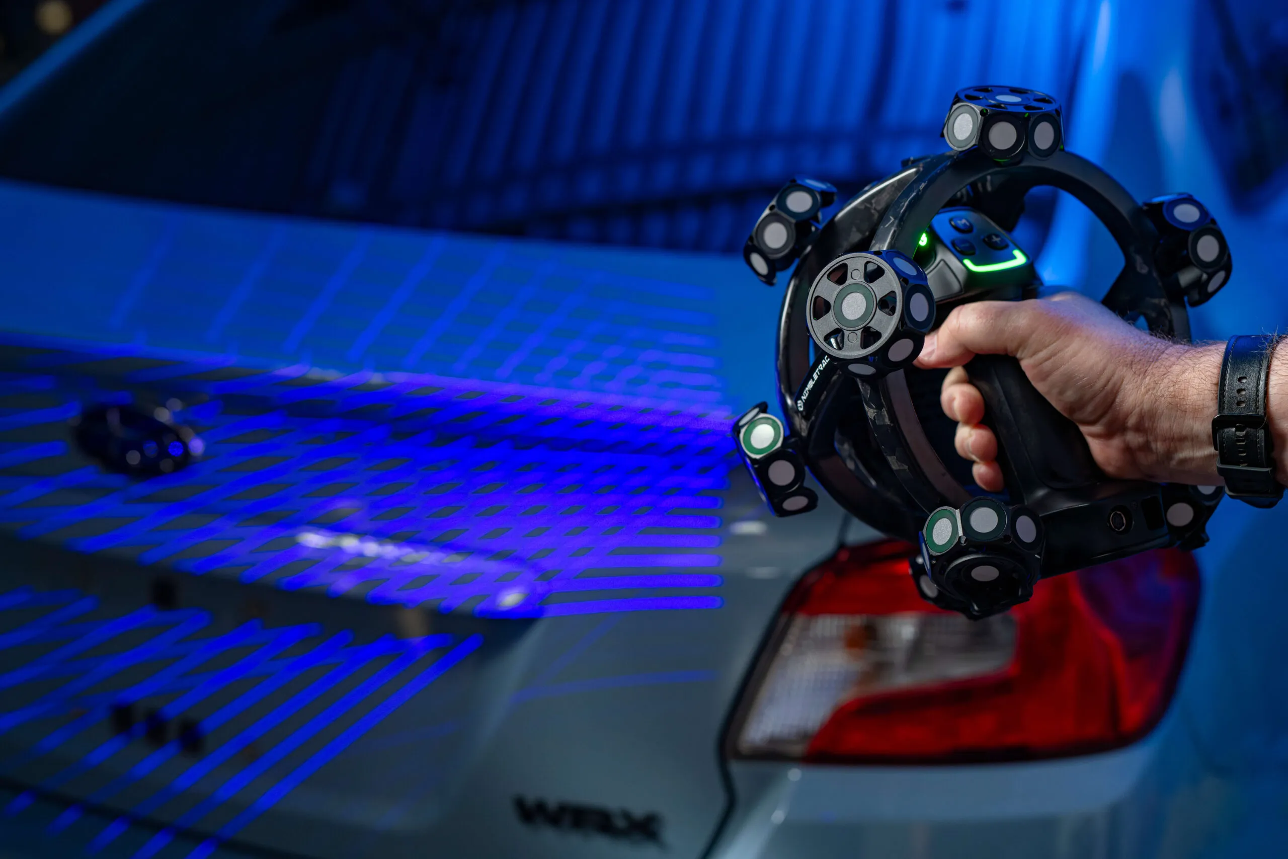
Scanning is not a universal replacement for a CMM, and the pitch that says otherwise is doing you harm. Tight bores, precision-machined features, and anything with a tolerance in the low microns still belong on a CMM. Optical systems measure surfaces they can see, and a deep hole is not a surface a camera sees well. Threads are worse. Where the tolerance is tight and the feature prismatic, a touch probe is more accurate and cheaper to defend.
Scanning also does not fix a bad datum scheme. If your GD&T is ambiguous, full-field data makes it worse, because now you can produce ten deviation maps from ten defensible alignments and argue about which is real. And it does not solve process problems. It tells you a panel is out. It does not tell you the fixture is worn. The people who get value from this already had a process for acting on measurement. The ones who did not end up with a scanner and reports nobody reads.
The technical integration is the easy part. The organizational integration is where programs stall.
Start with alignment strategy, because it decides every number downstream. Best-fit and datum-based alignment give two different answers about the same part, and both are correct. Best-fit answers “is this part the right shape.” Datum alignment answers “will this part function in the assembly.” Report the wrong one and you will either scrap good parts or ship bad ones. Write down which alignment applies to which characteristic before you scan anything.
Then handle correlation. If the CMM has been the authority for ten years, the scanner will disagree with it somewhere, and the first time it does, the scanner loses by default. Run correlation studies on real parts and understand the disagreement before it is a customer issue. Usually it is measurement definition, not accuracy.
Gage R&R deserves specific attention. Scanning R&R is not CMM R&R with a different fixture. Operator technique, surface prep consistency, and ambient light all contribute variation the CMM never had. That is defensible for PPAP, but it has to be studied rather than assumed. Auditors are comfortable with optical metrology. They are not comfortable with a study that pretends the method has no operator component.
Finally, decide who owns the data. Scans are large, and a quality system where the only copy lives on the metrology laptop is not a quality system. Sort out storage and retention early. Retrofitting it later is miserable.
The reason we push this order, definition first, correlation second, hardware third, is that we both sell the scanners and run them on customer parts as a service. The engineers writing this get the call when a system is not producing numbers anyone trusts, and that call is almost always about the first two steps rather than the third.
If you are working through any of this, a die tryout loop that keeps costing you passes, a sealing surface you cannot inspect properly, or a decision about whether to automate a measurement you currently do by hand, we are happy to talk it through with your parts and constraints in front of us. Tell us what you are trying to decide and we will give you a straight read on whether scanning helps, including when it does not. Get in touch and we will pick it up from there.
You have a part on the bench and no drawing for it. Or you have the drawing, and now you

For most of the twentieth century, a crime scene was preserved with a tape measure, a roll of film, and
If you have ever searched for a way to turn a physical object into a digital model, you have probably
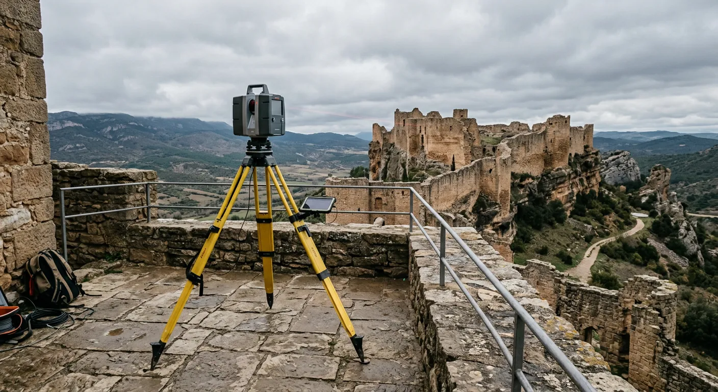
Every artifact and monument is on a clock. Stone weathers, pigments fade, bronze corrodes, and a single earthquake, flood, or