How Does 3D Scanning Work? A Beginner’s Guide to the Technology
You have a part on the bench and no drawing for it. Or you have the drawing, and now you

Ask three quality engineers whether they should buy a coordinate measuring machine or a 3D scanner, and you’ll get three different answers, usually shaped by whatever technology they already own. The honest answer is that 3D scanning vs CMM is rarely an either/or decision. Each tool measures the physical world in a fundamentally different way, and each one wins decisively in scenarios where the other struggles. The trick is matching the method to the part, the tolerance, and the throughput you actually need.
This guide breaks down the real differences between the two: points versus surfaces, submicron accuracy versus 25-micron point clouds, the speed gap on full-surface inspection, and the total cost of ownership most spec sheets ignore. By the end you’ll have a concrete decision framework for choosing the right approach on a part-by-part basis, plus a look at the hybrid workflows that let high-performing quality labs use both technologies together.
A coordinate measuring machine inspects a part one point at a time. A touch probe (or in some configurations a high-accuracy scanning probe) physically contacts the surface at discrete, operator-defined locations, and each contact returns an extremely precise XYZ coordinate. To inspect a hole, you take a handful of points around its diameter; to check a plane, you sample several points across the face. The CMM then fits geometry to those points and compares the result to nominal. It is deterministic, traceable, and deeply tied to the engineering drawing: you measure exactly the features the print calls out, and nothing else.
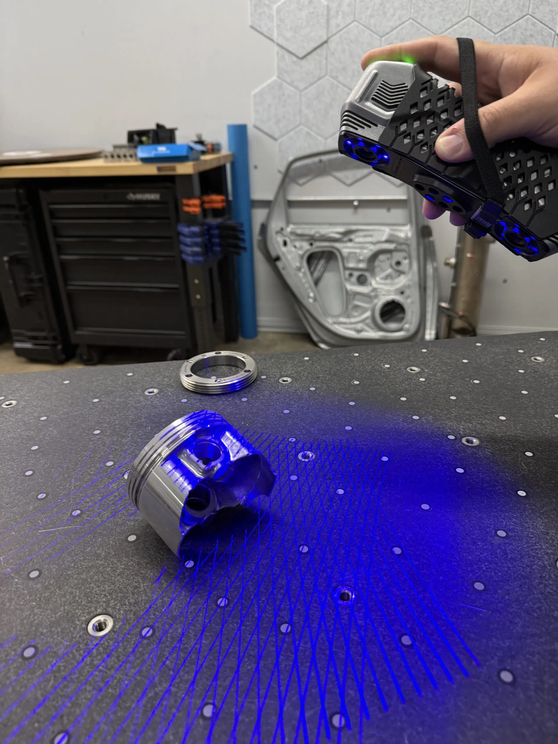
A 3D scanner works the opposite way. Instead of a few hundred deliberate points, an optical scanner captures millions of points in seconds, blanketing the entire visible surface to produce a dense point cloud and, ultimately, a polygon mesh. You aren’t sampling a feature. You’re digitizing the whole part. That difference in philosophy drives everything downstream. CMMs excel at answering narrow, precise questions (“is this bore in position to 0.01 mm?”). Scanners excel at answering broad ones (“how does this entire formed panel deviate from CAD across every square millimeter?”).
Neither is “better.” They produce different kinds of truth. A CMM gives you sparse, supremely accurate data tightly aligned to print callouts. A scanner gives you a complete digital twin of the as-built surface. Understanding that points-versus-surfaces distinction is the foundation for every other comparison below, and the reason both belong in a mature metrology and 3D inspection toolkit.
Accuracy is where CMMs earn their reputation. A well-maintained, climate-controlled bridge or gantry CMM routinely achieves volumetric accuracy in the single-digit micron range, with the best machines resolving features to a fraction of a micron. That level of certainty, backed by ISO 10360 verification and traceable calibration, is why CMMs remain the reference standard for tight dimensional and geometric tolerances. When a print calls out a bore diameter at ±0.005 mm, the CMM isn’t just adequate. It’s often the only instrument that can credibly certify the result.
Modern optical 3D scanners are far more accurate than most people assume, but they live in a different band. High-end structured-light and laser systems typically deliver point accuracy in the range of 25 to 30 microns, with the best metrology-grade units reaching into the low teens under ideal conditions. A portable measuring arm such as the Scanology AccuArm bridges the two worlds. It brings CMM-style hard-probe accuracy to the shop floor while also serving as a scanning platform, which makes it a useful reference point in this comparison.
A few things matter more than the headline number:
Accuracy vs. repeatability. A CMM is both highly accurate and highly repeatable on individual features. Scanners trade a little single-point accuracy for enormous data density, which can actually improve confidence on form and surface deviation because thousands of points characterize the surface rather than five.
Environment dependence. CMM accuracy assumes temperature control and a stable foundation. Scanner accuracy depends on calibration, surface finish, and good scanning technique. Shiny or dark surfaces may need a vanishing scanning spray to read reliably.
What you’re certifying. For a true-position callout on a critical fastener hole, the CMM’s submicron point wins. For overall surface conformance on a freeform part, the scanner’s full-field coverage tells a richer, more defensible story.
The accuracy advantage flips into a liability the moment you need to inspect a complex surface in full. Because a CMM measures point by point, fully characterizing a contoured part can mean programming hundreds or thousands of touches, then waiting while the probe travels between each one. A comprehensive inspection that touches every relevant feature on an organic or freeform component can stretch into hours.
A scanner captures that same part as a complete surface in a fraction of the time. An inspection that might take a CMM three to four hours of probing can often be scanned and aligned in 30 minutes or less, and the scan delivers far more coverage, not less. Instead of confirming that a few sampled points fall in tolerance, you get a full-surface color deviation map showing exactly where, and by how much, the part departs from CAD.
That throughput gap compounds across a production run. For first-article inspection of a multi-surface casting, for incoming inspection of formed sheet metal, or for any application where you need to see the whole part rather than a sampled subset, scanning’s speed advantage is decisive. Wireless and handheld systems push this further by removing fixturing constraints, and our 3D scanning services regularly turn around full-surface inspections in the time a touch-probe routine would still be warming up. When the bottleneck is inspection cycle time, surfaces beat points.
Capital cost is the conversation most teams start with, and here scanning generally holds an advantage. A comparable optical 3D scanning system can land at roughly half the initial investment of a high-accuracy CMM, before you account for the facility costs a CMM frequently requires: a climate-controlled room, a vibration-isolated foundation, and the floor space to host a fixed machine. Portable scanners and measuring arms, by contrast, go to the part instead of forcing the part to come to them.
But the sticker price is only part of the story. Real cost of ownership includes:
Programming and operator skill. CMM programming is a specialized discipline; building and validating routines takes trained staff and time. Scanning is generally faster to learn for capture, though extracting GD&T results from scan data still benefits from metrology expertise.
Software and licensing. Inspection software is an ongoing line item for both. A package like Geomagic Control X processes scan data into full dimensional and GD&T reports, and the same platform thinking applies whether the data came from a probe or a point cloud.
Throughput and labor per part. If scanning cuts a four-hour inspection to thirty minutes, the labor savings per part can dwarf the hardware difference within a single high-volume program.
Facility and maintenance overhead. CMMs carry environmental and calibration obligations that portable scanners largely avoid, though both require periodic verification to stay traceable.
The takeaway: scanners usually win on initial cost and labor-per-part, while CMMs justify their higher total cost when the application genuinely demands certified submicron accuracy.
For all the speed and cost advantages scanning brings, there are inspection problems where a CMM remains the correct, defensible answer. These tend to share a common trait: the tolerance is tighter than a scanner’s accuracy band, and the feature is prismatic enough to be defined by a handful of well-placed points.
When tolerances drop into the single-digit micron range (precision bores, bearing journals, ground shafts, sealing faces), you need an instrument whose accuracy comfortably exceeds the tolerance you’re certifying. A scanner working at 25 to 30 microns simply cannot resolve a ±0.005 mm callout with the confidence required for sign-off. For these features, the CMM’s point-by-point precision is not negotiable. The deterministic, traceable nature of touch probing also makes CMM data easier to defend in audits and customer first-article reviews.
Many geometric callouts are best served by the CMM’s controlled, repeatable sampling. True position of a precision hole, roundness of a bore, cylindricity, and tight flatness on a small functional face all depend on accuracy that exceeds typical scanner resolution, and on the clean, deterministic geometry fits the CMM produces. If your team is still building fluency in interpreting these callouts, our GD&T basics training helps connect drawing requirements to the right measurement strategy. For the most demanding geometric tolerances on prismatic features, the CMM is the tool to reach for.
Scanning earns its place wherever the part is complex, the surface matters more than a few discrete points, or there’s no CAD model to probe against in the first place. In these scenarios, trying to force a CMM to do the job is slower, less informative, and sometimes outright impossible.
Turbine blades, impellers, molded plastics, ergonomic housings, medical and dental geometry, sculpted automotive surfaces, anything without clean prismatic features, plays directly to the scanner’s strength. There are no obvious “points” to probe on a continuously curving surface, so sparse sampling tells you little. A dense scan captures the entire contour and reveals deviation across the whole form, exactly the data a freeform part demands.
When a part exists but the CAD doesn’t, scanning is the natural starting point. A high-resolution scan becomes the basis for a faithful digital model, whether you’re recreating an obsolete component or modernizing an existing design. From there, scan-to-CAD tools turn that mesh into editable, parametric geometry. Our reverse engineering services and 3D CAD modeling services exist precisely for this workflow, where a CMM’s point data would be far too sparse to reconstruct an organic shape.
The single most compelling case for scanning is the full-surface color deviation map. Aligning a complete scan to the nominal CAD and visualizing every deviation across the entire part, in a single color-coded overlay, gives engineers an at-a-glance understanding that no table of probed coordinates can match. For warpage studies, formed-part conformance, weldment distortion, and tooling validation, this whole-part view is the deliverable that drives decisions.
The most capable quality labs stop treating this as a versus question and run the two technologies in concert. A common pattern: scan the part first to capture the complete surface and generate a full-field deviation map, then use a CMM (or a hard-probing portable arm) to certify the handful of critical, tight-tolerance features that demand submicron accuracy. The scan handles breadth, and the probe handles depth on the features that need it.
Hybrid hardware blurs the line even further. A portable measuring arm like the Scanology AccuArm can hard-probe a precision feature and capture scan data on the same setup, giving you both data types from a single fixturing. On the software side, processing both probe and scan data in a unified inspection platform such as Geomagic Control X means one report combines certified point measurements with full-surface analysis, with no stitching together results from disconnected tools.
This combined approach is how aerospace, defense, and other high-mix precision customers we work with get the best of both worlds: the throughput and completeness of scanning for the bulk of the part, and the certified accuracy of point measurement where the tolerance leaves no room for compromise.
Before you reach for either tool, run the part through these questions. The answers will usually point clearly to scanning, to CMM, or to a hybrid approach.
How tight is the tightest tolerance? If it’s tighter than roughly 25 to 30 microns, the CMM (or a hard-probing arm) should certify those features.
Is the geometry prismatic or freeform? Prismatic features with clear datums favor the CMM; organic, contoured, or sculpted surfaces favor scanning.
Do you need full-surface coverage or a few discrete features? Whole-part deviation analysis is a scanning job; a handful of critical callouts can be probed.
Does CAD already exist? No model means reverse engineering, so start with a scan.
What’s your throughput requirement? High part volumes and short cycle times reward scanning’s speed.
What are the environmental constraints? Shop-floor or in-situ measurement favors portable scanners and arms over a fixed, climate-controlled CMM.
What does the customer or standard require? Some audits and first-article reviews expect traceable touch-probe data on specific characteristics.
Factor CMM 3D Scanning Data type Sparse, discrete points Dense full-surface point cloud / mesh Typical accuracy Submicron to single-digit microns ~25 to 30 microns (best units lower) Inspection speed (complex part) Hours of probing Often 30 minutes or less Best for Tight-tolerance prismatic features, critical GD&T Freeform surfaces, reverse engineering, full-surface deviation Relative initial cost Higher; often needs controlled facility Roughly 50% less; portable options Portability Typically fixed Handheld and arm-based options Ideal role Certify critical features Characterize the whole part
Used together, these answers rarely leave you guessing. The strongest quality programs match the method to the characteristic, and increasingly, they own both.
Because we sell and support both portable measuring arms and a full range of 3D scanners (and run an in-house metrology lab), our team has no incentive to push you toward one technology over the other. We help quality engineers and plant managers choose the right approach for each part, whether that’s a hard-probing Scanology AccuArm for tight-tolerance features, a fast optical scanner for full-surface work, or a hybrid setup unified in Geomagic Control X.
If you’d rather outsource the work, our metrology and 3D inspection services deliver certified, customer-ready reports without the capital outlay. Either way, the best next step is a conversation about your actual parts and tolerances. Contact us for a consultation or a quote, and we’ll help you build the right inspection strategy, not just sell you a box.
You have a part on the bench and no drawing for it. Or you have the drawing, and now you
A fender comes off the press and something is off. The hole pattern checks out on the CMM and every

For most of the twentieth century, a crime scene was preserved with a tape measure, a roll of film, and
If you have ever searched for a way to turn a physical object into a digital model, you have probably