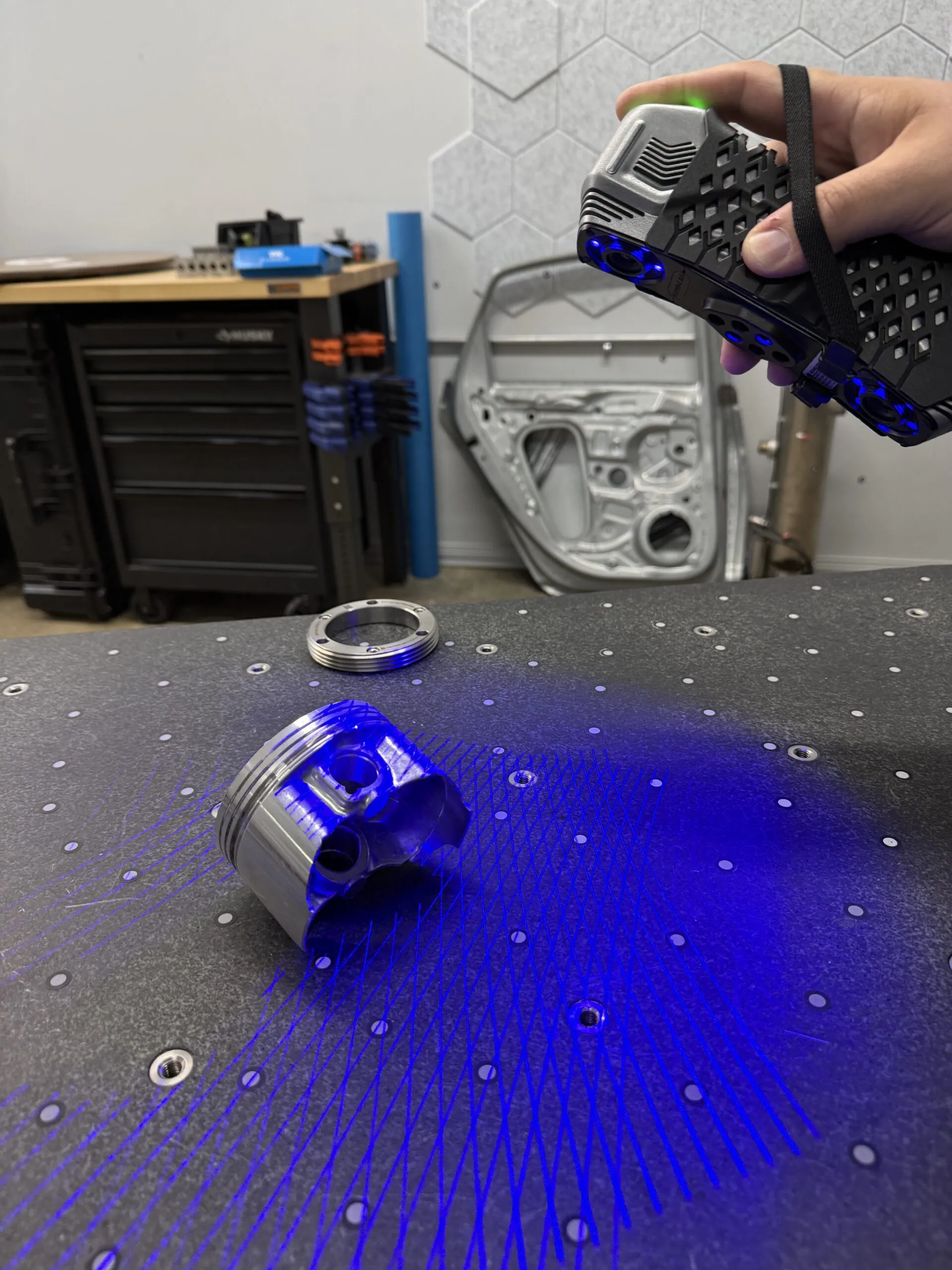
How Does 3D Scanning Work? A Beginner’s Guide to the Technology
You have a part on the bench and no drawing for it. Or you have the drawing, and now you

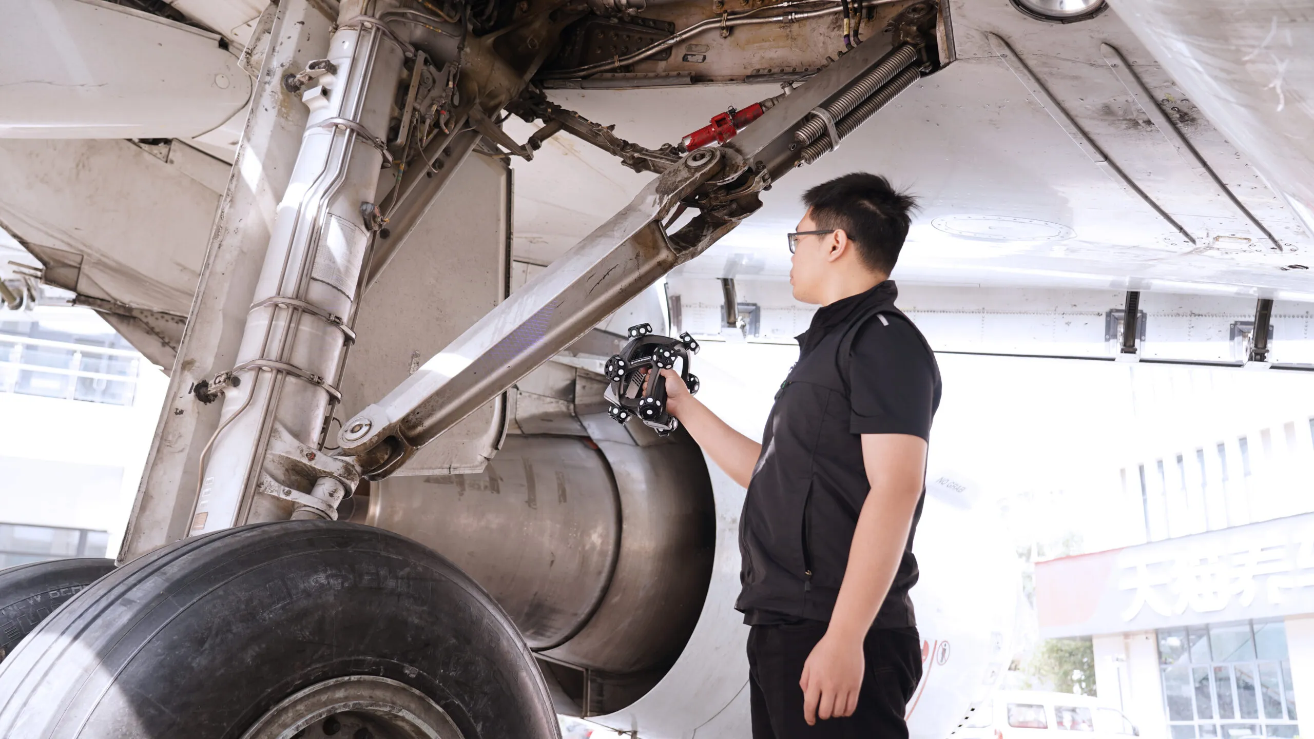
An aging aircraft rarely come with a complete paper trail. By the time a structural bracket, an actuator housing, or a landing gear fitting reaches its third or fourth overhaul cycle, the original drawings may be archived in a format no one can open, owned by an OEM that no longer supports the platform, or simply gone. 3D scanning for aerospace MRO and legacy parts closes that gap: it lets maintenance, repair, and overhaul shops capture the exact as-built geometry of an in-service component, assess damage against a known-good reference, and rebuild a manufacturable model when no original CAD data exists.
This article walks through the practical workflows MRO engineers use every day: damage assessment for dents, corrosion, and foreign object damage; reverse engineering discontinued components like landing gear, engine mounts, and nacelles; choosing a scanner that survives a working hangar; and the documentation and traceability considerations that keep your data defensible. The goal is a clear, technical picture of how scanning turns an undocumented part back into something you can inspect, repair, and reproduce.
Military and commercial fleets routinely fly airframes that are 30, 40, or even 50 years old. The platforms outlive their supply chains. Suppliers consolidate or close, OEMs end support, tooling is scrapped, and the engineering data, if it was ever digital, sits on media no current system can read. When a part fails or reaches its service limit, the MRO facility is left holding a physical component and no authoritative geometry to repair or remanufacture it from.
The problem compounds at the part level. A single fitting may have been revised across several configurations over its life, hand-fitted at assembly, or shimmed in the field, so even where a “drawing” exists it may not match the part on the bench. For low-volume, high-criticality components (structural brackets, hydraulic manifolds, gearbox housings, control-surface hinges) there is no economical way to re-source a few units through traditional channels. The realistic options are to fabricate from the existing part, repair it, or qualify a new source, and all three start with the same prerequisite: an accurate, trustworthy digital model of the geometry you actually have.
Manual measurement was never built for this. Calipers, height gauges, and hand layout can dimension a simple feature, but they fall apart on the organic, blended, and freeform surfaces common to aerospace castings, forgings, and sheet-metal assemblies. A nacelle inlet lip, a curved engine mount, or a contoured wing rib carries surface transitions and fillets that no stack of point measurements will ever fully describe. The result is a “reconstructed” drawing that captures a handful of dimensions and guesses at everything in between.
Touch-probe CMMs are accurate but slow and access-limited. They struggle with thin walls, soft or delicate surfaces, and deep or shadowed features, and they typically require the part to come to the lab rather than the lab coming to the part. For damaged components the situation is worse: a dent, a corrosion pit, or an FOD strike is a continuous surface deviation, not a discrete feature, and you cannot probe a defect you have not first located. Aging aircraft also present a documentation problem that no measuring tool solves on its own. Without a reference model, there is nothing to measure against. Traditional methods give you numbers; what an MRO program needs is a complete, comparable surface and a defensible record of it.
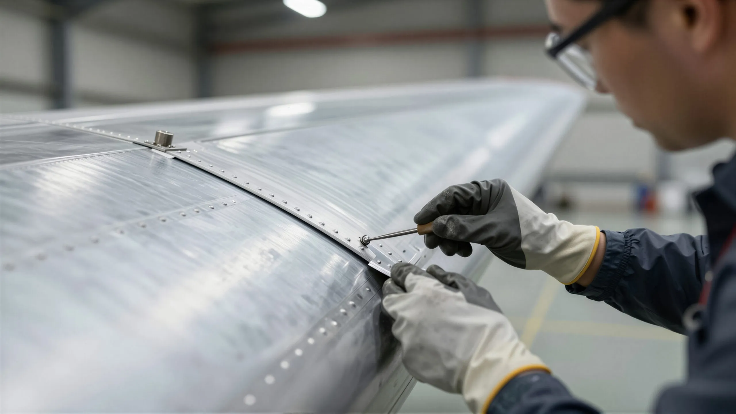
The first and highest-volume use for scanning in MRO is condition assessment. When a component comes off an aircraft, the question is rarely “what are its nominal dimensions.” It is “how far has this part deviated from where it should be, and is that within limits?” A non-contact 3D scan answers that by capturing the full surface as a dense point cloud or mesh, typically millions of points, which you then compare against a reference: an OEM model where one exists, a scan of a pristine exemplar, or a reverse-engineered nominal you have built and validated.
Because scanning captures the whole surface rather than sampled points, it sees damage you would otherwise miss and quantifies damage you already suspect. That makes it well suited to repeatable, documented disposition workflows, and it integrates cleanly with the kind of metrology and 3D inspection services that aerospace quality teams rely on for first-article and in-service evaluation.
The core technique is 3D deviation analysis: color-map comparison between the scanned part and a reference surface. Inspection software such as Geomagic Control X or PolyWorks|Inspector aligns the two datasets and renders the difference as a heat map, where green is within tolerance and warm or cool colors flag material added or lost. This turns subjective visual inspection into measurable, repeatable data.
Dents and deformation: A color map shows the depth and footprint of an impact or blend-out region, so an engineer can measure whether a dent exceeds allowable depth-to-diameter limits without scraping or shimming a gauge across it.
Corrosion and material loss: Pitting and exfoliation appear as localized negative deviation. Scanning quantifies how much wall thickness or surface material is gone, which is critical for disposition against minimum-thickness and remaining-life criteria.
Foreign object damage (FOD): Nicks, gouges, and strikes on blades, vanes, and leading edges are captured as discrete surface deviations, with measurable depth and location for repair-versus-scrap decisions.
Distortion and fit: Whole-part comparison reveals warpage, twist, and flatness or profile errors that explain assembly fit problems but never show up in point measurements.
The practical payoff is traceability. Every scan-based inspection produces a timestamped record of the part’s condition at that moment, which feeds repair planning, supports trend monitoring across overhaul cycles, and gives quality a defensible artifact for the airworthiness file.
When a part is obsolete and undocumented, scanning becomes the front end of a reverse engineering pipeline that ends in a manufacturable model. The workflow is consistent: scan the physical part, clean and align the mesh, then rebuild it as either a high-fidelity surface model or a fully parametric, feature-based CAD body depending on how the part will be produced and revised downstream. Scan-to-CAD platforms like Geomagic Design X and QuickSurface are built specifically for this: extracting regular geometry (planes, cylinders, holes, fillets) as editable features while preserving freeform regions as accurate surfaces. Our team delivers this end to end through our reverse engineering services and 3D CAD modeling services.
The output you want depends on intent. For a one-off replacement to be cut on a CNC, a watertight surface or solid may be enough. For a part you expect to revise, re-tolerance, or qualify across configurations, a clean parametric model with proper design intent is worth the extra effort, because it lets engineering change features without re-scanning. From that model the part can be reproduced by CNC machining, additive manufacturing, or conventional fabrication, and the same digital nominal then becomes the reference for inspecting every unit you make.
These three families illustrate the range of geometry MRO reverse engineering has to handle:
Landing gear components: Trunnions, side stays, torque links, and axle fittings are heavy, high-strength, often machined-from-forging parts with tight cylindrical and bore tolerances. They demand a model where the regular features are captured parametrically and the load paths are faithfully represented.
Engine mounts: Mount rings, links, and brackets combine machined interfaces with structural geometry and frequently carry as-built rework. Capturing the true contact surfaces and hole patterns matters more here than any nominal drawing.
Nacelles and cowlings: Inlet lips, fan cowls, and thrust-reverser structures are large, thin-walled, freeform aerostructures. These are surface-modeling problems first, where the goal is an accurate, fair surface that respects the original aerodynamic contour.
The defining reality of legacy work is that the part on the bench is the master. There is no CAD to defer to, so the scan must capture the as-built condition faithfully, including hand-fitted surfaces, field rework, and the small departures from any original intent that have accumulated over decades. A good reverse engineering process distinguishes between what is true design intent (a hole that should be round and on-center) and what is incidental (local distortion you should not bake into the model), and it documents the assumptions either way.
This is also where the line between “as-built” and “nominal” has to be drawn deliberately. Scanning a worn or damaged part and modeling it exactly reproduces the wear; modeling it to an idealized intent may not fit the mating hardware. Experienced reverse engineering resolves this by building the parametric model to clean design intent while validating it back against the scan data and against known mating features, so the reproduced part both installs correctly and carries a rational, inspectable geometry.
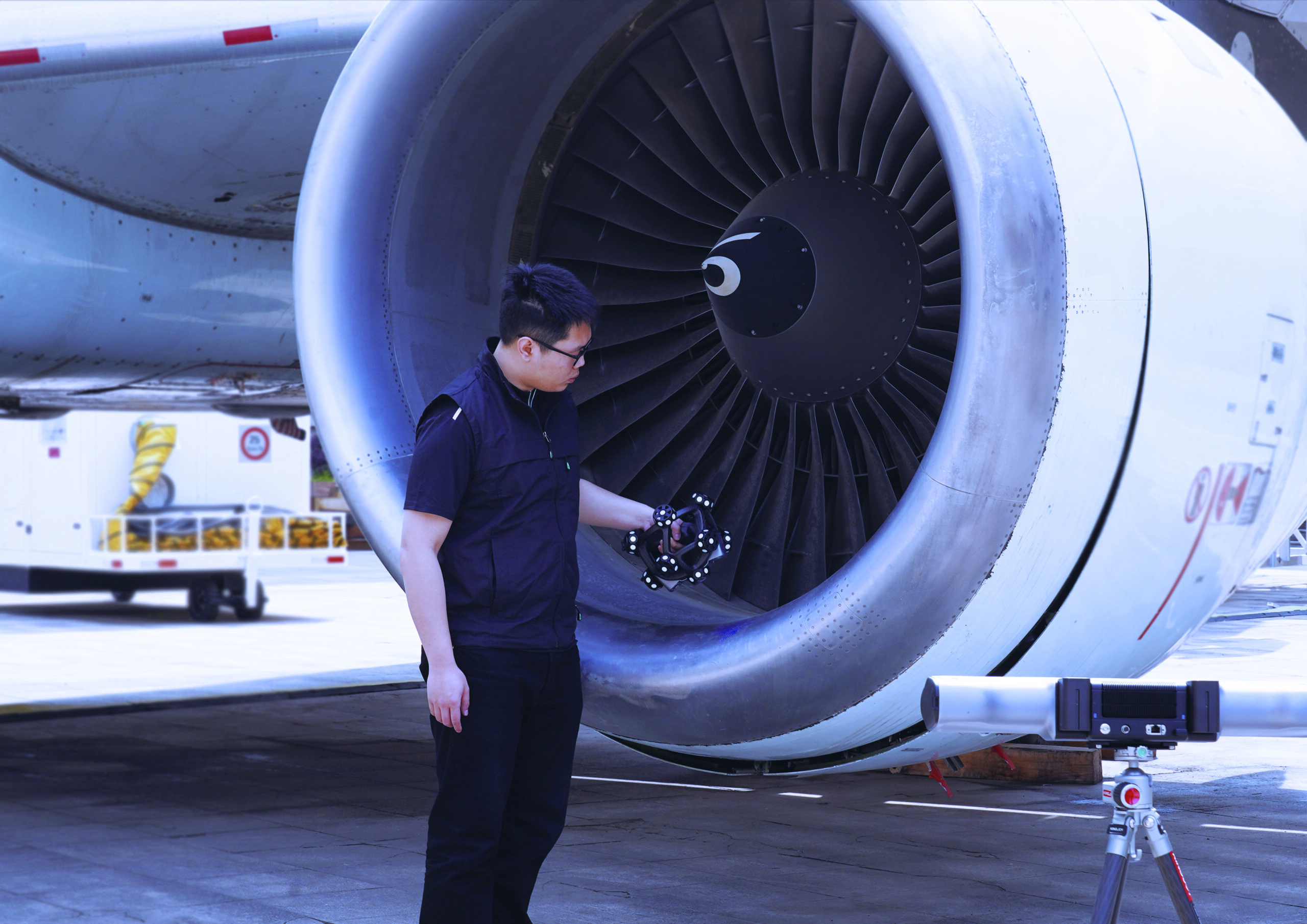
Scanner selection for MRO is driven less by headline accuracy numbers and more by the working environment and the part mix. A hangar or back shop is not a metrology lab: there is ambient light, vibration, dust, temperature swing, and parts that range from a fist-sized fitting to a full nacelle section. The scanner has to come to the part, work in that environment, and span that size range. In practice most aerospace MRO programs end up with a small toolkit rather than a single device, and the right starting point is usually a portable system from our range of portable and handheld 3D scanners.
Reflective, polished, or dark aerospace surfaces (bare aluminum, anodized fittings, titanium) are notoriously hard to scan. A light, removable matting agent helps enormously, and self-vanishing scanning sprays such as AESUB Blue give a uniform matte coat that sublimates away cleanly, leaving no residue on flight hardware, which is important when you cannot risk contaminating a part you are about to return to service.
The central hardware decision is handheld optical scanning versus a portable measuring arm (a portable CMM). They solve different problems, and many shops run both.
Consideration Handheld optical scanner Portable measuring arm / CMM Best for Freeform surfaces, full-field capture, large or organic parts, damage mapping Prismatic features, precise hole/bore/datum measurement, hard-probe access Speed over large area Very fast: captures whole surfaces in a pass Slower: point-by-point or guided scanning along the arm reach Reach / part size Walk-around; effectively unlimited with reference targets Limited to arm envelope (typically a few feet) per setup Hangar tolerance Handles ambient light and movement well; wireless options aid access Very stable and accurate, but needs a solid mounting setup Typical role Damage assessment, reverse engineering of contoured aerostructures Verifying critical datums, bores, and machined interfaces
A wireless handheld such as the Artec Leo is well suited to walking around a large assembly in a hangar with no cables and no separate computer, while a system like the Scanology NimbleTrack offers tracked, high-accuracy capture across larger volumes. For shops that also need contact metrology on critical bores and datums, a portable arm such as the Scanology AccuArm brings probe-based precision and scanning into one tool. The right mix depends on your parts; if you are not sure, our team can scope it against your actual workload, and you can browse the full lineup of 3D scanners for reverse engineering to see the options side by side.
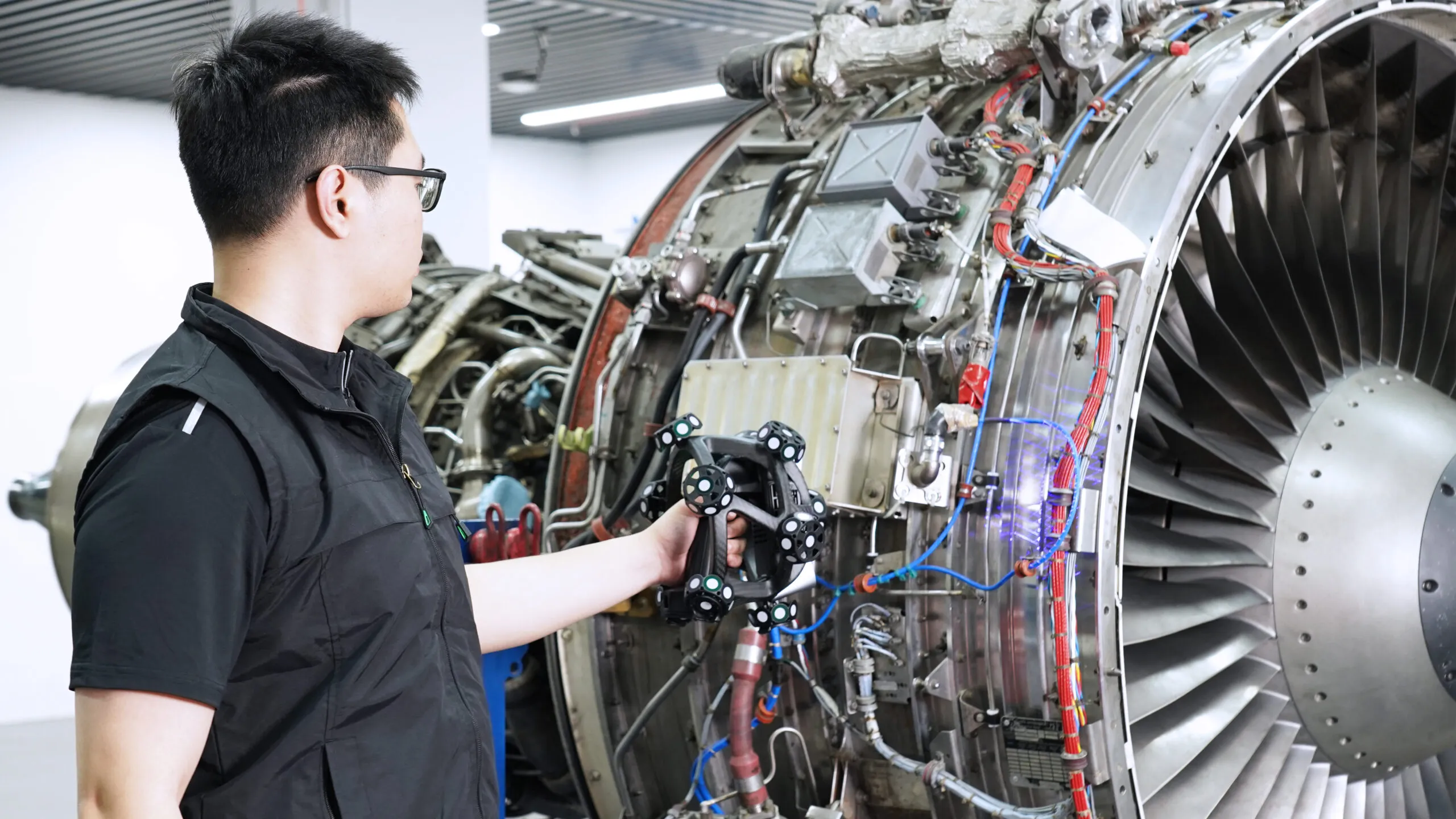
In aerospace, the scan is only as valuable as the record around it. Reverse-engineered and scan-inspected parts live inside a regulated system (FAA airworthiness rules, AS9100 quality management, and customer or military process specifications), and the central concept is traceability. You must be able to show how a number was produced: what instrument captured it, how that instrument was calibrated and verified, what alignment and reference were used, and who approved the result. A pretty color map with no measurement plan behind it is not evidence.
Building that into the workflow means a few disciplines become non-negotiable:
Instrument verification: Scanners and arms need documented calibration and periodic accuracy verification, ideally against traceable artifacts, so measurement uncertainty is known and recorded.
Defined measurement plans: Datums, alignment scheme, and tolerances should be specified before scanning, not chosen after, so inspections are repeatable and comparable across overhaul cycles.
GD&T literacy: Translating scan data into pass/fail dispositions requires correct application of geometric dimensioning and tolerancing; teams that are rusty here benefit from formal GD&T basics training.
Data retention and revision control: Raw scans, aligned datasets, the nominal model, and the inspection report should be archived together and version-controlled, so the airworthiness file can be reconstructed later.
Engineering authority: Reverse-engineered geometry still has to be approved through the proper engineering and airworthiness channels; scanning produces the data, but disposition remains an engineering decision.
None of this is unique to scanning. It is simply how regulated metrology has always worked. The advantage of a scan-based process is that it generates a richer, more complete, and more easily archived record than manual methods ever could.
Consider the common scenario of a discontinued structural bracket with no usable drawing. The traditional path, hand-measuring features, drafting a reconstructed print, iterating when the first article does not fit, can stretch across weeks and still leave gaps wherever the geometry was freeform or hand-fitted. It is slow precisely because manual measurement struggles with exactly the surfaces aerospace parts are full of.
A scan-driven path collapses much of that. Capturing the full part takes minutes; reverse engineering it to a clean parametric model is a focused modeling task; and the same scan doubles as the inspection reference for the reproduced part. The compression comes from not re-deriving geometry by hand and from catching fit problems in software before metal is cut. Across the aerospace and defense customers we work with, this kind of shift commonly turns a multi-week reconstruction into a small number of days. Just as importantly, it produces a reusable digital master so the next time that bracket is needed, the model already exists. The exact savings depend on part complexity and your existing process; the point is that scanning removes the slowest, least reliable steps from legacy remanufacture.
There are two sensible ways into scan-based MRO, and the right one depends on volume and cadence. Partnering with a service provider makes sense when legacy work is occasional, when you need a specific part turned around quickly, or when you want validated reverse-engineered models without standing up an in-house program. You get expert capture, modeling, and inspection, and a defensible deliverable, without buying hardware or training staff. Bringing equipment in-house makes sense when the workload is steady and recurring: when scanning becomes part of routine inspection and remanufacture, owning a system and developing internal expertise pays off and keeps sensitive parts and data inside your facility.
Partner first when the need is project-based, when you want to prove the workflow before investing, or when a complex aerostructure demands experience you do not yet have on staff.
Buy and build internally when scanning is a repeatable, high-frequency activity, when security or ITAR considerations favor in-house data handling, or when you want metrology available on demand in the back shop.
Do both: many programs start with services to handle the hard parts and a purchased handheld for everyday damage assessment, scaling capability as the program matures.
Whichever path fits, the underlying capability is the same: turning an undocumented physical part back into trustworthy digital geometry you can inspect, repair, and reproduce.
Digitize Designs supports aerospace MRO at both ends of that decision. If you need parts captured, modeled, and validated, our 3D scanning services, reverse engineering services, and metrology and inspection services turn legacy components into manufacturable, inspectable CAD, even when no OEM drawings exist. If you are building an in-house program, we can match the right portable scanner and inspection software to your hangar environment and part mix, and train your team to use them with confidence.
We work with aerospace and defense customers on exactly these legacy-parts and damage-assessment challenges every day. To scope a specific part, a recurring workflow, or an equipment package, contact our team for a consultation or quote. Bring us a part with no documentation, and we will show you the path back to a trustworthy model.
You have a part on the bench and no drawing for it. Or you have the drawing, and now you
A fender comes off the press and something is off. The hole pattern checks out on the CMM and every

For most of the twentieth century, a crime scene was preserved with a tape measure, a roll of film, and
If you have ever searched for a way to turn a physical object into a digital model, you have probably