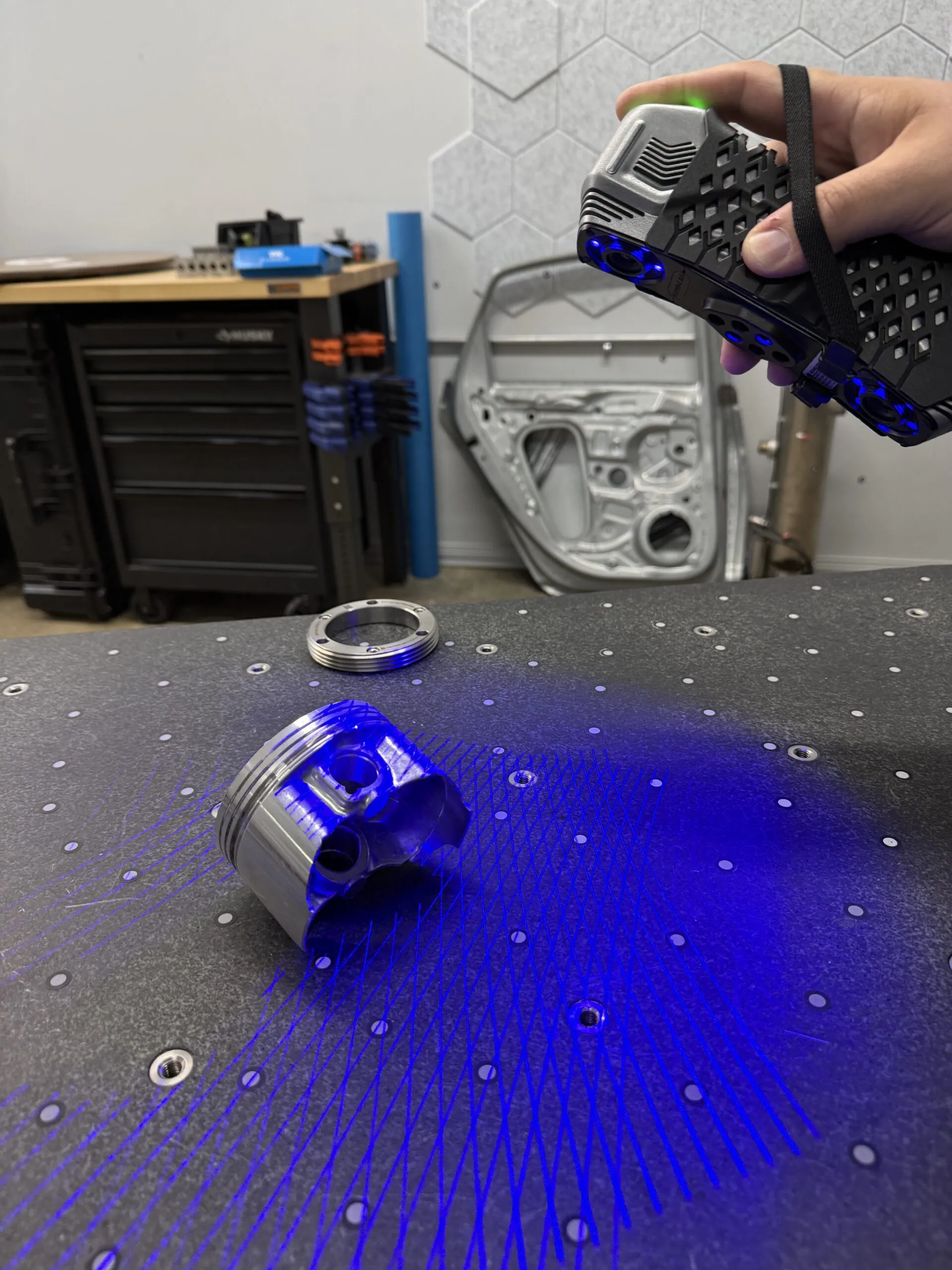
How Does 3D Scanning Work? A Beginner’s Guide to the Technology
You have a part on the bench and no drawing for it. Or you have the drawing, and now you

A 3D scanner gives you millions of measured points. What it does not give you is an editable CAD model. Bridging that gap is the job of the scan to CAD workflow: the disciplined process of turning a raw point cloud into a clean, dimensionally controlled, fully editable solid or surface model. Done well, it lets you recreate a legacy part with no drawings, redesign around an existing assembly, or feed a digitized prototype straight into manufacturing.
This guide walks through the entire pipeline end to end, from mesh prep to a parametric tree dropped into SOLIDWORKS. We will cover the two fundamental modeling philosophies, parametric and surfacing, when each one wins, how to combine them, and how to evaluate the software, including Geomagic Design X and QuickSurface, before you commit to a $15K+ purchase.
Scan-to-CAD is the conversion of measured 3D scan data, typically a polygon mesh built from one or more point clouds, into native CAD geometry: sketches, features, solids, and surfaces that an engineer can dimension, modify, and manufacture from. The mesh that comes off a scanner is a faithful record of the as-built object, but it is “dumb” geometry. There is no concept of a hole, a boss, a fillet radius, or a draft angle, just triangles. The scan to CAD workflow adds engineering intent back on top of that measured reality.
The people who need it span almost every discipline that touches a physical part:
If you regularly digitize parts in-house, scan-to-CAD software pays for itself quickly. If the work is occasional or the geometry is unusually demanding, it can make more sense to lean on our reverse engineering services rather than build and maintain the capability internally. Either way, understanding the workflow helps you scope the project correctly.
Every scan-to-CAD tool sits somewhere on a spectrum between two philosophies. Choosing the right one for a given part is the single most important decision you will make, because it determines how editable, how accurate, and how manufacturable the result is. Get it wrong and you will fight the geometry for the rest of the project.
Parametric modeling rebuilds the part the way a designer would have modeled it in the first place: with 2D sketches driven by dimensions, extruded and revolved into features, and organized in an editable feature tree. A 50 mm bore becomes a circle dimensioned to 50 mm and a cut-extrude, not a fitted cylinder of unknown intent. This is the right approach for the vast majority of mechanical, prismatic, machined, and molded parts, anything with planes, cylinders, holes, ribs, bosses, and constant-radius fillets.
The payoff is editability. Because the model carries design intent, you can change a wall thickness, adjust a hole pattern, or alter a draft angle downstream, and the model updates intelligently. You also get clean, regular geometry that manufactures predictably. The cost is effort: parametric reconstruction is more manual and demands an engineer who understands how the part was made. This is the core of professional 3D CAD modeling services, and it is where Geomagic Design X is strongest.
Surfacing takes the opposite approach. Instead of inferring sketches and features, it lays a network of mathematically defined NURBS (Non-Uniform Rational B-Splines) surfaces directly over the scan mesh, following its true shape point for point. There is no feature history and no design intent, just a high-fidelity skin that hugs the measured data, usually to within a controllable deviation of a few microns to a few hundredths of a millimeter.
This is the correct method for organic, freeform, and styled geometry: turbine blades, helmets, prosthetics, automotive body panels, sculpted consumer products, and worn or as-cast surfaces that never had a clean mathematical definition. Two variants exist. Auto-surfacing drapes a quad patch network over the entire mesh in minutes, ideal when you need a usable surface model fast and do not need to edit it parametrically. Manual or controlled surfacing lets you lay out the patch layout deliberately for cleaner, more editable surfaces. QuickSurface is purpose-built for exactly this kind of fast, accurate NURBS and hybrid work, and Design X includes capable auto-surface tools as well.
FactorParametricSurfacing (NURBS) Best forPrismatic, machined, molded partsOrganic, freeform, styled shapes OutputEditable feature tree, solidsSurface skin, fitted to mesh Design intentPreserved (dimensions, relations)None, geometry follows the scan Editability downstreamHighLow to moderate Accuracy to scanIdealized (snaps to clean geometry)Very high (hugs measured data) EffortHigher, more manualLower for auto-surface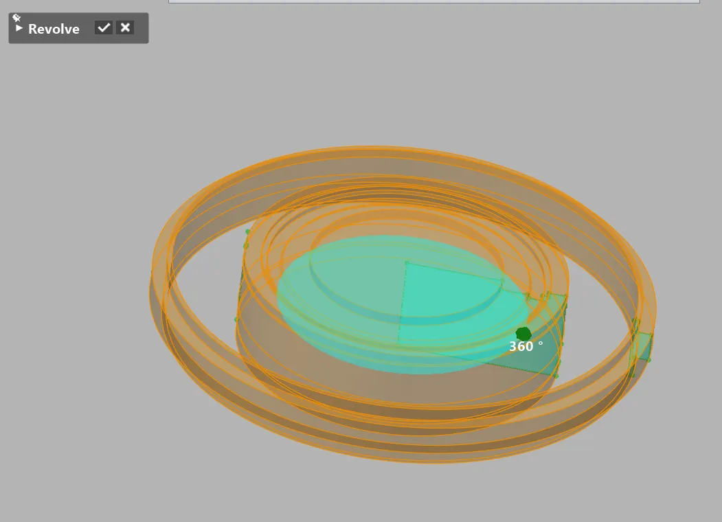
Regardless of which modeling philosophy you choose, the front half of the process is shared. Quality scan data and disciplined mesh prep determine the ceiling on your final model. The steps below describe the typical pipeline in Geomagic Design X, but the principles apply to any serious scan to CAD workflow.
The model is only as good as the mesh underneath it. Raw scan data arrives with noise, scanner artifacts, stray points, holes where the scanner could not see, and often redundant overlapping data from multiple passes. Before any modeling begins, the mesh needs to be conditioned:
This stage is unglamorous and frequently rushed, which is exactly why so many projects go wrong. A clean, well-aligned mesh makes every later step faster and more accurate. If the data itself is poor, no amount of modeling rescues it, which is why capture quality from professional 3D scanning services matters as much as the software.
Once the mesh is clean, the software analyzes its curvature to automatically segment it into regions, contiguous patches that correspond to a single geometric primitive: a plane, cylinder, cone, sphere, or freeform area. This region map is the skeleton of the reconstruction. From these regions, Design X can fit ideal geometry directly: it recognizes that a region is a cylinder and extracts its true axis and diameter, or that several regions share a plane and aligns them.
Good segmentation pays off immediately. Extracted reference geometry, planes, axes, and points, becomes the framework you build sketches and features against. The engineer’s judgment matters here: deciding which measured features represent real design intent (a bore that should be perfectly round and centered) versus manufacturing variation or wear that should be idealized away rather than faithfully reproduced.
For parametric reconstruction, the workhorse technique is slicing the mesh with cutting planes to generate cross-section polylines, then fitting clean sketch entities, lines, arcs, circles, and splines, to those slices. The software snaps the sketch to the underlying data while you apply dimensions and constraints so the sketch is fully defined and intentional, not a wobbly trace.
This is where measured reality becomes engineering geometry. A revolved part is captured by taking a single cross-section through its axis and fitting a profile to revolve. A complex housing is reconstructed plane by plane. The discipline of building clean, dimensioned, fully constrained sketches is what separates an editable model from a fragile one, and it is exactly the skill set our CAD modeling team applies daily.
With sketches and reference geometry in place, you build the solid the way you would model from scratch: extrude the main body, revolve the profile, cut the bores, pattern the hole array, add the bosses and ribs, and apply fillets and chamfers as features rather than tracing them as surfaces. Each step lands in the feature tree with its own dimensions and parent-child relationships.
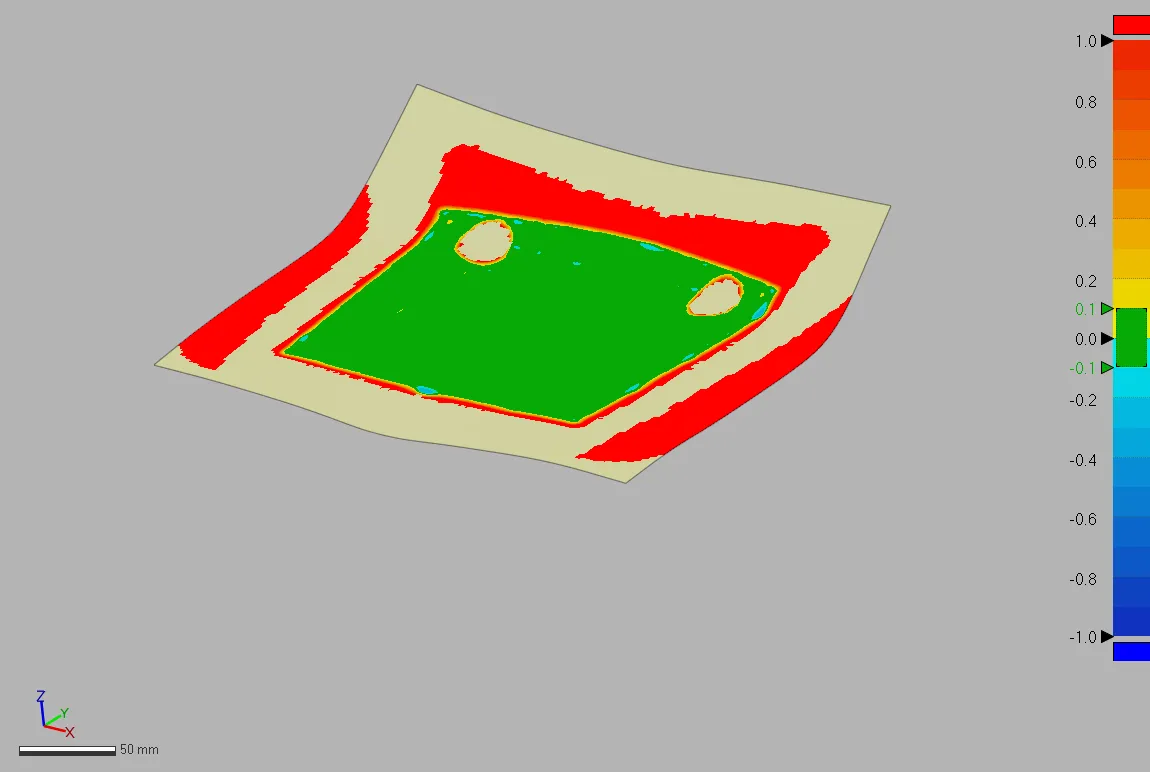
Throughout, Design X provides a live deviation analysis, a color map comparing your evolving CAD model back to the original scan mesh. Green means you are within tolerance; red means you have drifted. This running feedback lets you confirm in real time that your idealized model still honors the measured part, typically holding deviation in the tens of microns for well-scanned rigid geometry. It is the bridge between reverse engineering and metrology and 3D inspection: you are not guessing whether the model is right, you are measuring it.
A finished model is only useful if it lands in your CAD system in a form you can keep working with. The weak version of scan-to-CAD exports a dead solid body as a STEP or IGES file, geometry with no tree, no sketches, and no editability. The strong version preserves the work.
Geomagic Design X’s LiveTransfer does exactly that: it pushes the model into SOLIDWORKS (and other major CAD platforms) with the full feature tree intact, sketches, extrudes, revolves, patterns, fillets, and all, recreated as native SOLIDWORKS features. The engineer who receives the file can edit a dimension, suppress a feature, or drive a configuration as if they had modeled it natively. Design X also runs as an add-in directly inside SOLIDWORKS, so the round trip is seamless. For surfacing work, QuickSurface exports clean NURBS via STEP/IGES, and its hybrid models transfer solids plus reference geometry. Preserving editability through transfer is the entire point, and it is the feature most teams underweight when comparing tools.
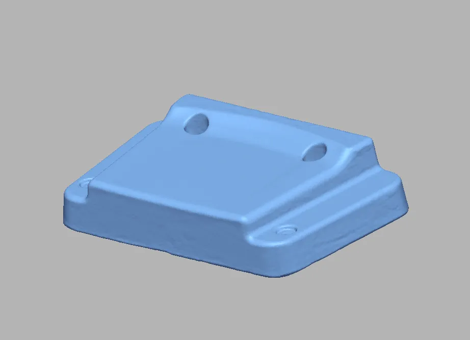
Most real parts are not purely prismatic or purely organic. A bracket might be machined planes and holes joined to a cast, free-flowing transition. A consumer product might have a styled outer shell over a parametric internal boss structure. Forcing such a part entirely into one approach produces either a stiff model that misrepresents the freeform areas or a surface skin you can never edit. The answer is a hybrid workflow.
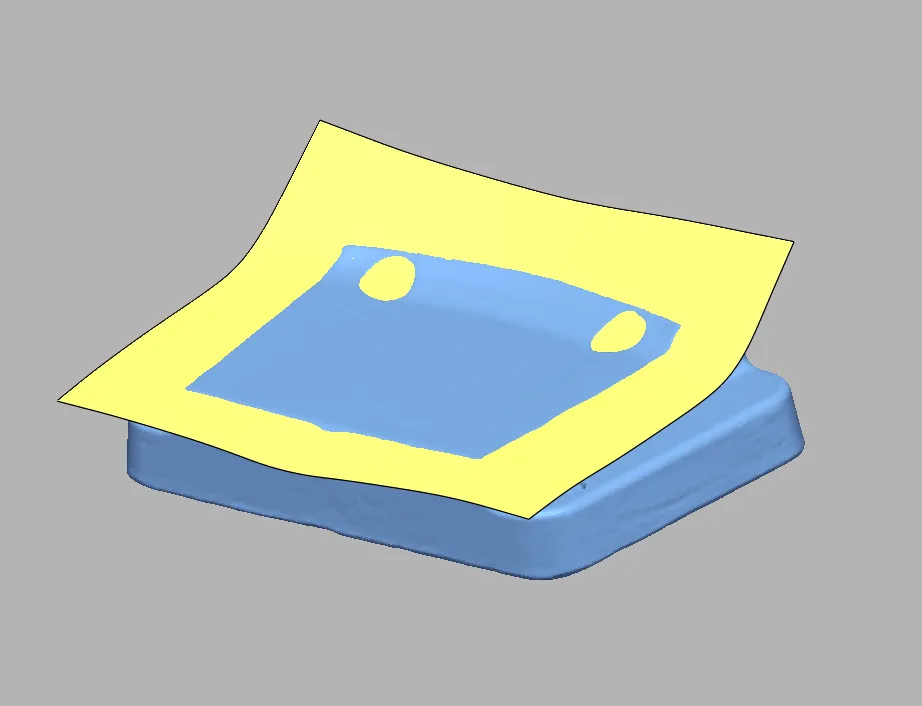
In a hybrid model, you reconstruct the regular features parametrically, sketches, extrudes, holes, fillets, and the organic regions as fitted NURBS surfaces, then stitch them into a single watertight solid. The practical rules of thumb:
Both Geomagic Design X and QuickSurface are built for this mixed approach, and choosing where to draw the line between parametric and surfaced regions is a judgment call that comes with experience. It is one of the clearest places where bringing in a specialist saves a project from a model that technically exists but cannot be used.
At the $15K+ tier, you are buying a long-term capability, not a one-off tool, so match the software to the work you actually do. The dominant choices we deploy are Geomagic Design X and QuickSurface, each with a clear sweet spot.
CapabilityGeomagic Design XQuickSurface Primary strengthFull parametric feature-based modelingFast NURBS surfacing and hybrid modeling Feature tree to CADYes, LiveTransfer with historySolid/surface export (STEP, IGES) Auto-surfacingYesYes, very fast SOLIDWORKS integrationAdd-in plus LiveTransferDirect transfer of bodies Mesh prep depthExtensiveSolid, more streamlined Best fitComplex prismatic and hybrid parts, full editabilityOrganic parts, fast turnaround, valueChoose Geomagic Design X when you need true parametric reconstruction with an editable feature tree and LiveTransfer into SOLIDWORKS, and when your parts are mechanically complex or you reverse engineer often. The Design X family also scales: Design X Plus adds advanced capabilities for the most demanding work, while Design X Go targets a more focused, accessible entry point. Choose QuickSurface when most of your work is organic or freeform, you value fast auto-surfacing and a strong price-to-capability ratio, and you do not need a parametric history on every part. Many shops own both. As for the alternatives, generic mesh-to-solid converters and basic CAD reverse-engineering add-ins exist, but they typically lack disciplined region recognition, live deviation analysis, and history-preserving transfer, the three things that make the difference between a usable model and a wasted week.
Scan-to-CAD projects rarely fail because the software was incapable. They fail because of avoidable process errors, usually upstream. The recurring offenders:
Every one of these is preventable with discipline and the right tooling. When tolerances are tight or the geometry is critical, it is also worth grounding the team in GD&T fundamentals so the model’s controlled features map cleanly to how the part is actually inspected and used.
Whether you are standing up an in-house scan-to-CAD capability or need a complex part reconstructed correctly the first time, our team can help you do it the right way. We sell and support the full Geomagic Design X family and QuickSurface, and our engineers use these tools daily across reverse engineering and 3D CAD modeling projects for manufacturing, aerospace, and defense customers we work with. We can recommend the right software and scanner pairing for your parts, train your staff on disciplined mesh prep and parametric reconstruction, or take the project off your plate entirely.
If you are evaluating a scan to CAD workflow or weighing a software purchase, talk to us first. Contact Digitize Designs for a consultation or a quote, and we will help you scope the approach, the tools, and the tolerances before you spend a dollar.
You have a part on the bench and no drawing for it. Or you have the drawing, and now you
A fender comes off the press and something is off. The hole pattern checks out on the CMM and every

For most of the twentieth century, a crime scene was preserved with a tape measure, a roll of film, and
If you have ever searched for a way to turn a physical object into a digital model, you have probably