Reverse Engineering Discontinued Parts: A Step-by-Step Guide for Manufacturers
August 21, 2026
Reading Time: 10minutes
In This Article
A pump bracket cracks on a 30-year-old packaging line. The OEM dissolved a decade ago, the drawings are gone, and the part number returns nothing but dead links. For maintenance managers, this is the recurring nightmare that idles production. Reverse engineering discontinued parts with 3D scanning turns that broken casting in your hand into a manufacturable CAD model and a steady supply of replacements, without the original prints and without the OEM.
This guide walks through the full process the way a working engineer actually runs it: capture, mesh repair, design-intent extraction, parametric CAD, verification, and manufacturing. We’ll also cover how to pick the right scanner for your part, the pitfalls hiding in worn surfaces, the legal questions you should ask first, and how to decide whether to build the capability in-house or hand it to a service.
When Reverse Engineering Makes Financial Sense
Reverse engineering is not free, so the first decision is economic, not technical. The case is strongest when a part is genuinely unavailable (discontinued, sole-sourced by a vendor who no longer exists, or buried in proprietary tooling) and when downtime carries real cost. A single line stoppage on a high-throughput process can burn more in a day than a complete scan-to-CAD-to-machined-prototype effort costs end to end.
The math usually favors reverse engineering when one or more of these conditions hold:
No OEM support: the manufacturer is out of business, the part is obsolete, or lead times have stretched to months.
Critical downtime: the component sits in the production path, and a failure stops the line.
Recurring need: you replace the same wear part on a predictable schedule, so a reusable CAD model pays back across many builds.
Improvement opportunity: the original failed by design, and you want to strengthen a fillet, change a material, or correct a known weak point while you’re in there.
No usable documentation: drawings were never digitized, or the only “spec” is a worn physical sample.
It makes less sense when an equivalent part is still cataloged and cheap, when tolerances are so tight that only the OEM’s controlled process can hold them, or when intellectual-property restrictions make reproduction a legal problem (more on that below). When the part is unavailable and the downtime is expensive, though, the question stops being whether and becomes how fast.
The Six-Step Reverse Engineering Workflow
A disciplined reverse engineering project moves through six stages. Skipping or rushing any one of them, especially mesh cleanup and design-intent capture, is where most amateur attempts produce a part that looks right but doesn’t fit or function. Here is the workflow our engineers follow, and the one you’ll run yourself if you bring scanning in-house.
Step 1: Capture the part with 3D scanning
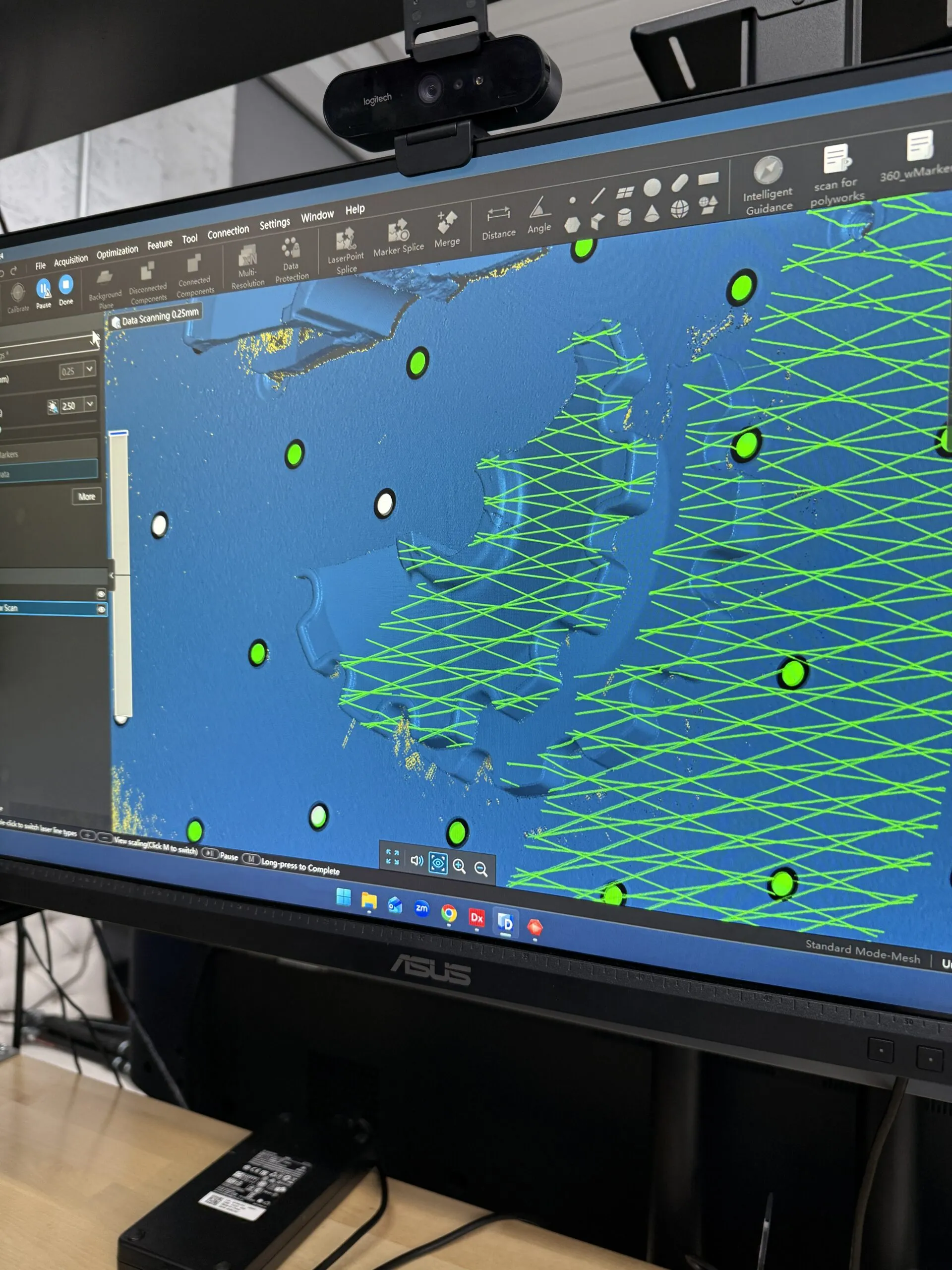
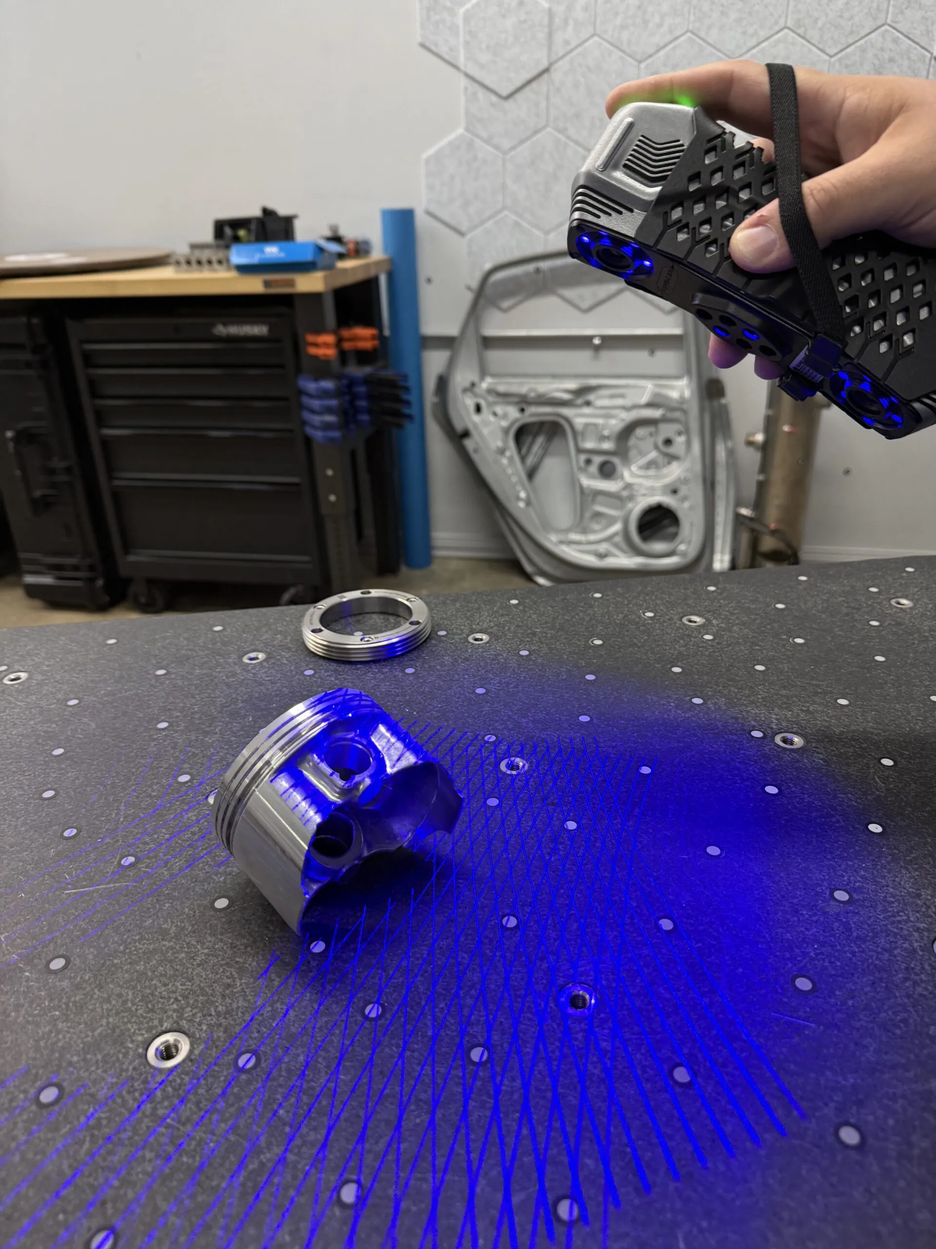
Everything downstream depends on the quality of the point cloud. The goal is a complete, dense, accurate capture of every functional surface (bores, mating faces, datums, sealing surfaces) with enough resolution to resolve the smallest feature that matters. A blue-light or laser-line 3D scanner collects hundreds of thousands of points per second and outputs a polygon mesh, typically holding accuracy in the 25–50 micron range for the systems built for this work.
Two capture details make or break this step. First, surface finish: shiny, dark, or translucent parts confuse optical scanners, so a thin pass of a vanishing scanning spray such as AESUB Blue renders the surface matte and self-removing within hours. Second, fixturing and coverage: rotate the part, capture deep features and undercuts, and use targets or geometry-based alignment so the multiple views stitch into one watertight model. If you don’t own a scanner, our 3D scanning services handle capture in our facility or on-site at yours.
Step 2: Clean and repair the mesh
Raw scan data is never perfect. It carries noise, stray points from the fixture or spray overspray, overlapping data from multiple passes, and holes where the scanner couldn’t see: inside bores, under flanges, in deep pockets. Before you can extract a single dimension, the mesh has to be cleaned into a reliable reference.
Noise reduction and smoothing, without rounding off the sharp edges and corners you’ll need as references.
Outlier removal: deleting disconnected clusters and floating points from spray, dust, or the holding fixture.
Hole filling: bridging gaps with flat, tangent, or curvature-matched patches depending on whether the underlying surface is planar or freeform.
Decimation and remeshing: reducing triangle count to a manageable size while preserving feature fidelity.
Alignment: orienting the mesh to a logical coordinate system, ideally to the part’s own datum features, so the CAD that follows is anchored to real functional references.
Resist the urge to “repair” geometry that’s actually damage. A filled hole that hides a worn pocket will propagate a bad dimension straight into your replacement part. Repair the scan artifacts; reconstruct the worn features deliberately in the next steps.
Step 3: Extract design intent, not just geometry
This is the step that separates a useful CAD model from an expensive digital paperweight. A scan tells you where the surface is; it doesn’t tell you what the designer meant. The bore that scanned at 24.97 mm was almost certainly a 25 mm nominal. The face that reads 2.3 degrees off parallel was meant to be flat. The fillet that measures a wandering 4.8–5.2 mm was a clean R5.
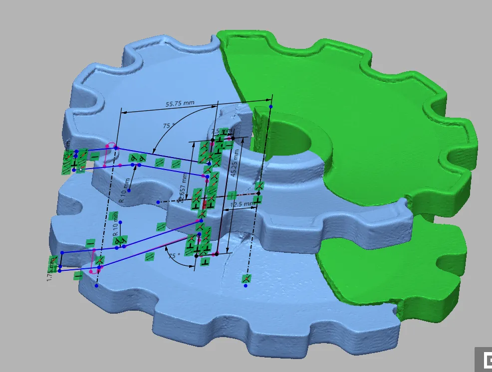
Capturing design intent means inferring those original nominal values and relationships (clean primitive features, true planes and cylinders, consistent radii, symmetry, and concentric or coaxial relationships) rather than blindly tracing every wobble in a worn casting. Measure several instances of a feature, look for the rational number the designer almost certainly used, and round to it. This judgment is exactly why reverse engineering is an engineering task and not a button you press, and it’s the core of our reverse engineering services.
Step 4: Build the parametric CAD model
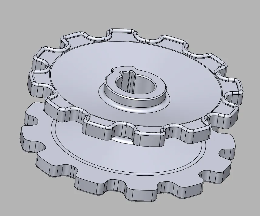
With the mesh cleaned and the intent understood, you build a true parametric, feature-based solid model (extrudes, revolves, sweeps, and patterns driven by editable dimensions) rather than a “dumb” surface wrap of the scan. Parametric reconstruction is what lets you later adjust a wall thickness, change a hole pattern, or convert the part to a new material with predictable results.
Scan-to-CAD tools accelerate this dramatically. Geomagic Design X fits regular geometry directly to mesh regions, auto-segments the scan into recognizable surfaces, and offers a guided solid-modeling workflow that often cuts modeling time roughly in half versus tracing by hand in a generic CAD package. The output is a clean, history-based model that exports to a native STEP or to your existing SOLIDWORKS, Creo, or NX environment. For organic or freeform parts, a hybrid approach pairs parametric features with high-quality surfaces, and our CAD modeling services can deliver the finished, drawing-ready model if you’d rather not staff the tooling internally.
Step 5: Verify the CAD against the scan
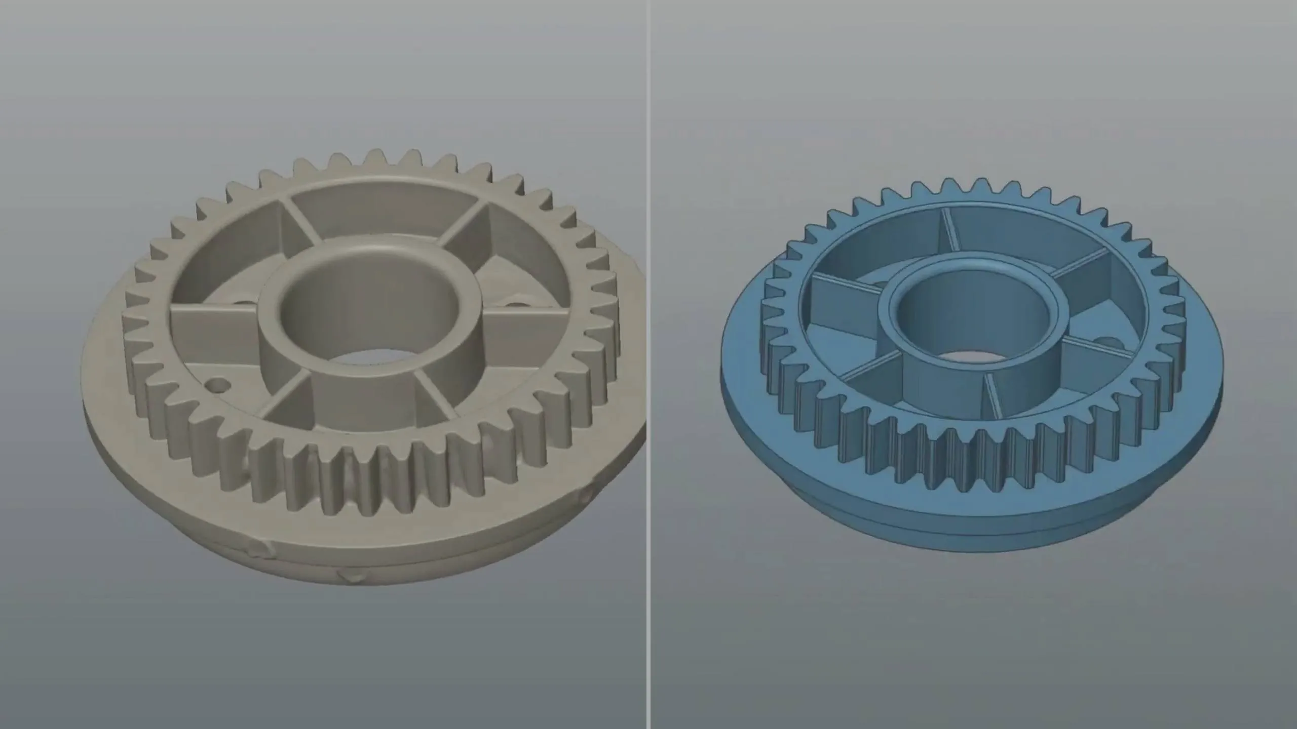
You don’t get to assume the model is right. You prove it. Verification overlays the finished CAD body back onto the original scan mesh and generates a color deviation map: green where the model matches the scan within tolerance, red and blue where it strays. This is your objective, documented confirmation that the reconstruction faithfully represents the real part.
A good verification pass answers concrete questions. Are all functional surfaces within tolerance, where typically you’d target deviations under a few hundredths of a millimeter on critical features? Where the model deliberately departs from the scan (a worn surface restored to nominal, a strengthened rib), is that departure intentional and documented? Inspection software such as Geomagic Control X or PolyWorks|Inspector produces the deviation report and, just as importantly, the same software supports first-article inspection of the manufactured replacement. If you need a formal, traceable inspection deliverable, our metrology and 3D inspection services close that loop.
Step 6: Manufacture: CNC, casting, or additive
The CAD model is the asset; the manufacturing route is a business decision driven by material, quantity, geometry, and lead time. The three common paths each have a clear sweet spot.
MethodBest forStrengthsWatch-outs
CNC machiningMetal parts, tight tolerances, low-to-mid volumeHigh accuracy and repeatability; full material properties; fast for prototypes and sparesCost rises with complexity; deep internal features may need special tooling
CastingComplex metal geometries at higher volumeEconomical per-part at scale; suits large or intricate shapesTooling/pattern cost and lead time; requires draft and shrink compensation in the model
Additive (3D printing)One-offs, prototypes, complex or consolidated geometryNo tooling; geometry freedom; fast turnaround; metal and engineering polymers availableAnisotropic strength; surface finish and tolerance may need post-processing
A common, pragmatic sequence: 3D print a fit-check prototype to validate the model in the actual assembly, then CNC machine the production spares from the same verified CAD. Because the model is parametric, you can add draft angles and a shrink factor for casting, or thicken a wall for additive, without rebuilding from scratch.
Choosing Your Scanner Based on Part Size and Complexity
There is no single best scanner. There’s a best scanner for your part. The dominant variables are physical size, the smallest feature you must resolve, surface finish, and whether you need to bring the scanner to a part bolted into a machine. Matching the tool to the job is the difference between a clean first scan and a frustrating afternoon.
As a rough decision guide:
Small, high-detail parts (connectors, gears, intricate castings under a hand-span): a high-resolution structured-light scanner such as the Artec Spider II resolves fine features down to tens of microns.
Medium parts and general-purpose work (brackets, housings, pump bodies): a versatile handheld like the Artec Leo or Artec Eva balances speed, accuracy, and coverage.
Shop-floor and large industrial parts: a wireless laser system such as the Scanology NimbleTrack handles big weldments and frames with high throughput.
Hard-to-reach features and probing: a portable measuring arm like the Scanology AccuArm adds touch-probe access to deep bores and datum points that optical scanners struggle to see.
Very large parts and full assemblies (machine frames, room-scale equipment): a long-range LiDAR scanner such as the Artec Ray II captures meters of geometry accurately.
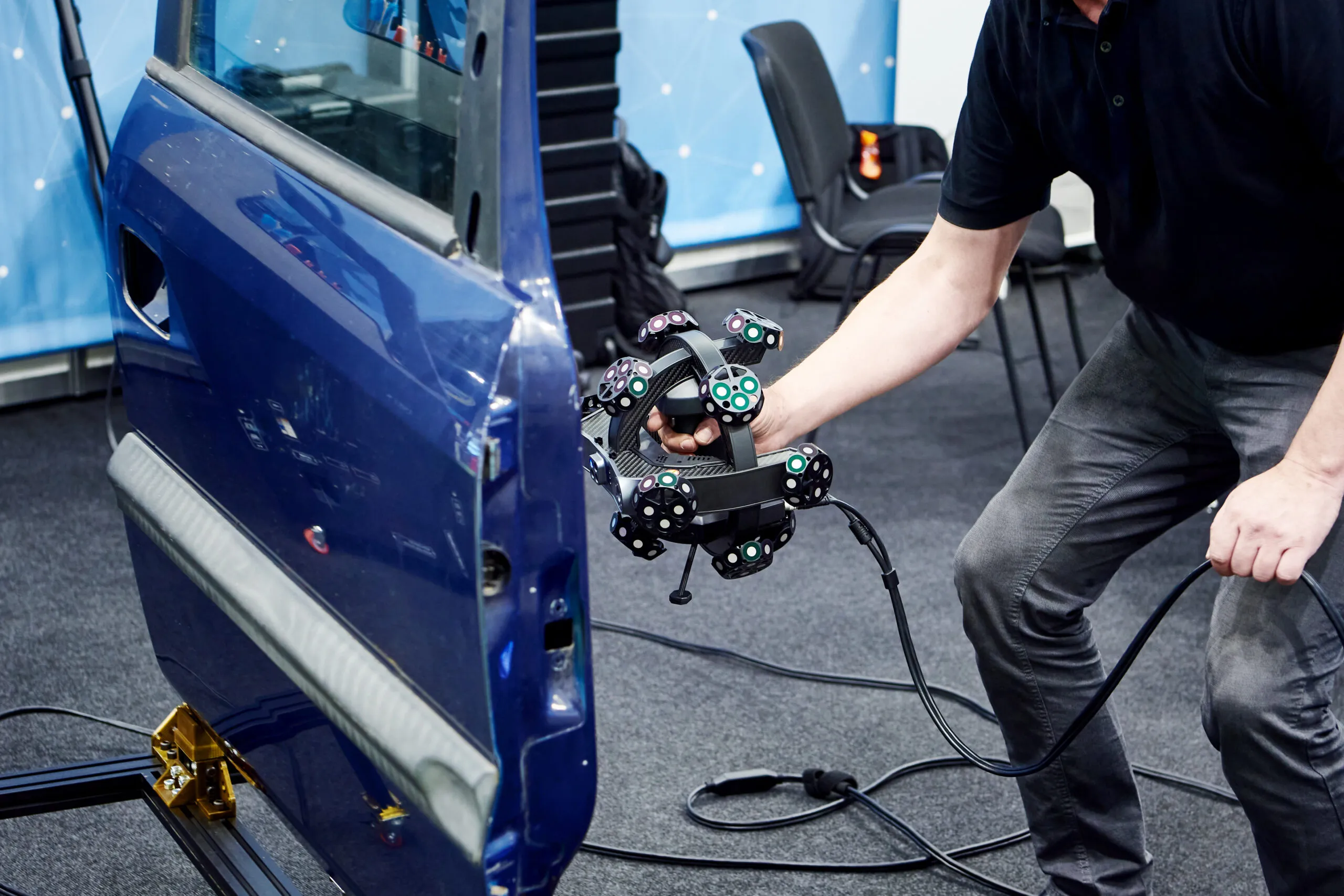
If you’re evaluating hardware for a reverse engineering program rather than a one-off, our 3D scanners for reverse engineering and portable handheld scanner lineups group systems by exactly these use cases. The right answer is often a small kit (one detail scanner and one general-purpose handheld) that covers the range of parts a maintenance shop actually sees.
Common Pitfalls: Worn Surfaces and Missing Features
The single biggest trap in reverse engineering legacy parts is reproducing the part’s damage instead of its design. The sample in your hand has lived a hard life: bearing journals are worn undersize, sealing faces are scored, threads are stripped, sharp edges are rounded from handling, and a corner may be cracked or missing entirely. Scan it faithfully and you’ll faithfully copy decades of wear into a brand-new part that fits worse than the one you replaced.
Guard against it with deliberate technique:
Restore worn surfaces to nominal. A shaft journal that scans at 24.96 mm but should mate with a 25 mm bearing gets modeled at the original nominal, not the worn measurement. Measure the unworn datum features and back-calculate intent.
Reconstruct missing material logically. Use symmetry, repeated features, and the part’s mating geometry to rebuild a broken corner or a snapped boss that the scan can’t show.
Find a better sample when you can. If two or three worn parts exist, scan all of them. Wear rarely occurs identically, and comparing them reveals the original geometry.
Watch the surface-finish failure modes. Shiny, dark, or translucent areas drop out of optical scans, leaving holes precisely where you can least afford guesswork. Treat them with the right spray (AESUB Violet for medical and food-contact parts, AESUB Diamond for the finest detail) rather than filling the gap in software after the fact.
Probe what you can’t see. Deep blind bores, internal threads, and tight pockets are often better captured with a touch probe or measuring arm than with line-of-sight optics.
Every one of these calls is a judgment about original intent. Document the deviations you introduce, and verify the final model against both the scan and the part’s mating components before you cut metal.
Legal Considerations: IP and Reverse Engineering
Reverse engineering is broadly lawful, a long-recognized practice for interoperability, repair, and competition, but “broadly lawful” is not “always permitted for this specific part.” Before you reproduce a component, take a few minutes to understand the intellectual-property landscape around it. This is general guidance, not legal advice; when stakes are high, run the part by counsel.
The questions worth asking:
Patents: Is the part or a feature of it covered by an unexpired patent? Copying patented technology can infringe even if you derived the geometry independently. Most discontinued parts on legacy equipment are well past the ~20-year patent term, but verify rather than assume.
Functional vs. ornamental: Purely functional dimensions generally aren’t protectable, but distinctive ornamental designs may carry design-patent or trade-dress protection. Copying the function is safer ground than copying a branded aesthetic.
Trademarks: Reproduce the geometry, not the logo. Never replicate the OEM’s name, part markings, or branding on your replacement.
Contracts and licenses: Service agreements, software EULAs, and purchase terms sometimes contain anti-reverse-engineering clauses. A right that exists by default can be signed away.
Repair vs. reconstruction: Producing spare parts to maintain equipment you own sits on far stronger footing than manufacturing parts to resell in competition with the original maker.
For the typical maintenance scenario, keeping your own out-of-support equipment running with replacement spares, the legal risk is usually low. The risk climbs when the part is recent, the design is distinctive and branded, or you intend to sell copies. When in doubt, document that the part is obsolete and unavailable, and get a legal read before scaling up production.
Should You Do It In-House or Outsource?
Once you’ve reverse engineered a few parts, the strategic question is whether to own the capability. There’s no universal answer. It turns on volume, the breadth of parts you encounter, and whether you have (or can develop) the engineering judgment that steps 3 through 5 demand. The hardware is the easy part; the skill is reading design intent and verifying the result.
FactorBring it in-houseOutsource to a service
VolumeFrequent, ongoing reverse engineering across many partsOccasional or one-off needs
Upfront costScanner, software, and training as a capital investmentPer-project fee, no capital outlay
Turnaround controlImmediate response to a line-down event, on your scheduleDependent on the provider’s queue
Skill requiredYou build and retain scanning + CAD + metrology expertiseExpertise and edge-case judgment come with the service
Part complexityBest once your team has reps on harder geometriesIdeal for difficult, high-stakes, or unfamiliar parts
A hybrid model works well for many manufacturers. Outsource the early and the hard parts to build confidence and get fast wins, then invest in a scanner and Geomagic Design X once the volume justifies it, bringing the routine spares in-house while sending the genuinely tricky jobs out. Training matters as much as tooling; reverse engineering and downstream inspection both lean on solid measurement fundamentals, which is why a course like our GD&T basics training pays off across the whole program.
How Digitize Designs Can Help
Whether you need a single discontinued part reproduced this week or you’re standing up an in-house reverse engineering capability, we can meet you at either end. Our engineers run the complete scan-to-CAD-to-verification workflow as a turnkey service, and we’re the people who sell and support the scanners and the Geomagic Design X software when you’re ready to own it. From handheld scanners to metrology-grade inspection, we’ll help you match the right tool to the parts your shop actually breaks.
If you have an obsolete part with no OEM behind it, send us the details. Explore our reverse engineering services or contact our team for a consultation and a quote. We’ll tell you honestly whether to scan it yourself or let us handle it.
SCHEDULE
Talk to a metrology consultant
Free 30-min scoping call to find the right scanner for your workflow.
QuickSurface AI launches November 17, 2026 as part of QuickSurface Pro 2027, turning 3D scans into editable parametric CAD models. Here is the release date, pricing, which editions include it, and the first teaser videos.