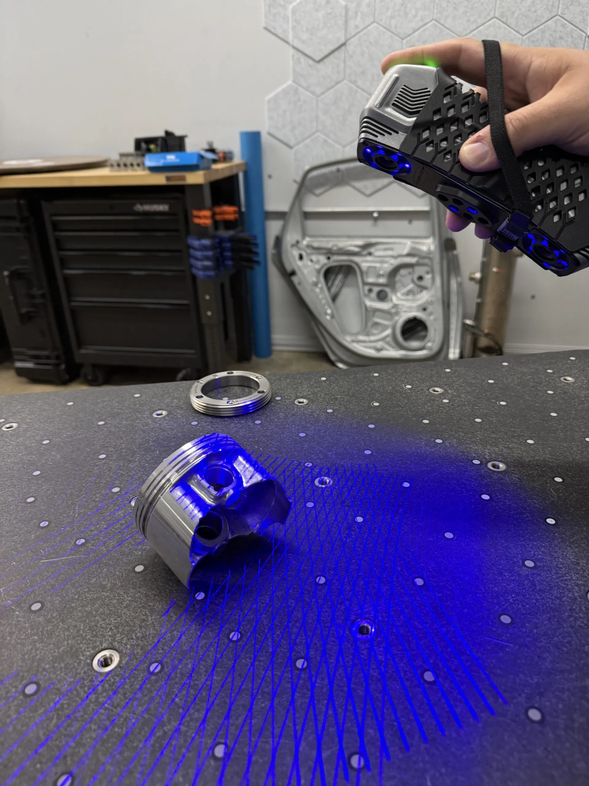
How Does 3D Scanning Work? A Beginner’s Guide to the Technology
You have a part on the bench and no drawing for it. Or you have the drawing, and now you

Quality teams are being asked to inspect more parts, to tighter tolerances, with the same or fewer people. Automated 3D inspection quality control, running optical scanning, alignment, and GD&T evaluation without an operator standing at the machine, is how high-volume manufacturers are closing that gap. This article walks through what “lights-out” inspection actually means, the four building blocks of an automated inspection cell, how to script unattended runs in Geomagic Control X, how to handle parts that fail, the throughput you can realistically expect, and a phased plan to get from a single pilot part to full production.
It is written for plant managers and QA directors who need to scale inspection capacity without scaling headcount. The technology is mature, but the difference between a cell that runs all night and one that jams at 2 a.m. comes down to a handful of engineering decisions made up front.
“Lights-out” describes a process that runs unattended: the lights in the room can literally be off. Applied to dimensional inspection, it means a part is presented to a scanner, captured, aligned to its CAD model, evaluated against a defined set of GD&T callouts and dimensions, and reported as pass or fail, with no human touching a keyboard during the cycle. The operator’s job shifts from running every measurement to loading parts, clearing exceptions, and reviewing trends.
It helps to separate three levels of automation, because vendors often use the same word for very different capabilities:
Scripted/repeatable inspection. The measurement routine is saved and replayed identically every time, but a person still triggers each run and handles the part. This removes operator-to-operator variation but not labor.
Unattended batch inspection. A queue of parts is processed back-to-back from a fixed or robot-mounted scanner with software-driven sequencing. A person loads a tray or magazine and walks away.
Fully integrated cell. Part handling, scanning, evaluation, reporting, and pass/fail sorting are linked, often with PLC or line communication, so the cell feeds a conveyor or sorts to good/scrap/rework bins on its own.
True lights-out inspection lives in the second and third tiers. The goal is not to eliminate engineers. It is to take the repetitive, deterministic part of the job and let it run on its own so your skilled people spend their time on first-article work, root-cause analysis, and process improvement.
The driver is rarely a single number. It is the combination of capacity, consistency, and labor that makes automated 3D inspection quality control pay off. Manual inspection on a touch-probe CMM is accurate but slow and operator-dependent; a complex part can take 20 to 45 minutes per piece, and a queue of parts waiting for the CMM becomes a bottleneck that holds up shipping.
Optical scanning changes the economics in three ways:
Speed. A structured-light or laser scan captures the entire surface in seconds to a few minutes, versus point-by-point probing. For parts with many features, full-field capture is often dramatically faster than a touch CMM measuring each point.
Consistency. A scripted routine measures the same features the same way on every part. Gauge R&R improves because the operator variable is largely removed.
Coverage. Because you capture the whole surface, you can add or revise dimensional checks later from archived scan data without re-measuring the physical part, which is useful when a customer requests additional data or an escape needs investigating.
The headcount argument is the one that resonates in the budget meeting. A cell that runs a second or third shift unattended effectively adds inspection capacity without adding inspectors, and it does so during hours when skilled metrologists are hard to staff anyway. When you model the return, weigh it against your real constraints: scrap caught earlier, reduced overtime, faster first-article turnaround, and the cost of an escape reaching a customer. For teams still leaning on manual gauging, our metrology and 3D inspection services are a low-risk way to benchmark scan-based inspection against your current method before you buy a cell.
Every automated inspection cell, regardless of brand, is built from four subsystems: a scanner, a part-handling mechanism, inspection software with an automation engine, and an output layer that reports results and talks to the rest of the line. Get all four right and the cell runs all night. Underspecify any one and it becomes a babysitting job. The sections below cover each in turn.
The first decision is how the scanner sees the part. There are two architectures, and the right one depends on part complexity and mix:
Fixed scanner with a moving part. A stationary structured-light scanner looks down at a rotary table or indexing fixture; the part rotates and tilts to present each face. This is simpler, cheaper, and extremely repeatable for parts that can be fully captured in a handful of orientations: stampings, machined plates, small castings.
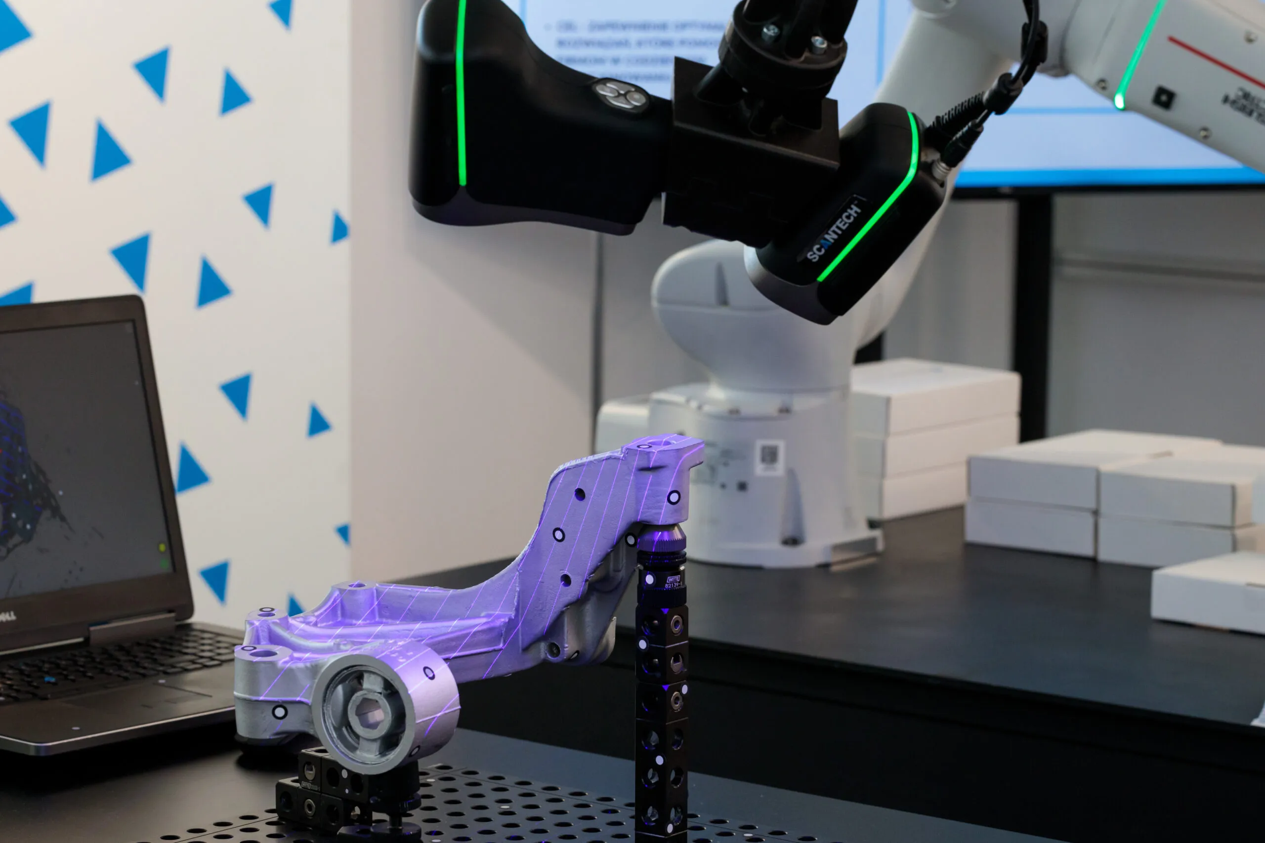
Robot-mounted scanner. The scanner rides on a six-axis robot arm that moves around a fixed part, capturing complex geometry, deep pockets, and undercuts from many angles. This handles larger and more intricate parts and supports a wider product mix, at the cost of more programming and integration.
Both approaches need a scanner with the accuracy and resolution your tolerances demand, typically structured-light systems holding in the range of tens of microns. The Digitize Designs RM-300 automated mobile inspection workstation packages a metrology-grade scanner, controlled motion, and inspection software into a single mobile cell, which sidesteps a lot of the integration risk of assembling a cell from loose components. For shops that want to start with a fixed-scanner concept and validate it, our industrial 3D scanners for manufacturing line covers the hardware end.
Part handling is where most lights-out projects succeed or fail, because automation only works if presentation is repeatable. A scan is only as good as the part’s position when it is captured, and exception handling almost always traces back to a part that was loaded slightly wrong. The common options:
Rotary or tilt-rotary table. Best for symmetric or prismatic parts captured by a fixed scanner. Inexpensive and very repeatable.
Indexing fixture or tray/magazine. A nest of identical fixtures holds a batch of parts in known positions; the operator loads a full tray and the cell works through it.
Robot arm for load/unload. A robot picks parts from a bin or conveyor, places them in the scan fixture, and removes them after evaluation: the route to a continuous, line-integrated cell.
Whatever the mechanism, design the fixturing so a part can only seat one way, and so its nominal position is repeatable to well inside your scan accuracy. Reference targets or a known datum feature on the fixture let the software find the part reliably even if seating varies slightly. Spending engineering time here pays back every single night the cell runs.
The brain of the cell is inspection software that can run a complete routine without prompts. This is where Geomagic Control X earns its place: its automation engine and Visual Scripting let you build a measurement program once and replay it across thousands of parts, including triggering capture, alignment, GD&T evaluation, pass/fail logic, and report generation. PolyWorks|Inspector offers comparable macro-driven automation for teams already invested in that ecosystem.
The capabilities that matter for unattended operation are: scripted or macro-based playback, branching logic so the software can react to what it measures, an automation/server interface so an external system (a PLC, robot controller, or scheduler) can launch and parameterize runs, and templated reporting. Without branching and an external interface, you have a fast manual routine, not a lights-out cell.
The fourth component is the output layer: what the cell does with a result once it has one. At minimum, every part should produce a stored report (PDF and a machine-readable export such as CSV or QIF) tagged with serial or batch ID, so trends and SPC charts build automatically. Beyond storage, integration choices include:
PLC / line signaling. A pass/fail digital signal tells a sorting gate or robot where to place the part: good, scrap, or rework.
SPC / quality-system feed. Results push to your SPC software or MES so out-of-trend conditions are caught before they become out-of-tolerance.
Alerting. When a part fails or the cell faults, an email or text goes to the on-call engineer with the report attached, so a 2 a.m. problem is waiting in their inbox, not discovered at 8 a.m.
Designing the output layer up front is what turns a scanner that measures parts into a quality system that protects your shipments.
Visual Scripting in Geomagic Control X is a node-based automation tool: you assemble a flow of operations (import scan data, initial and best-fit alignment, feature extraction, GD&T evaluation, tolerance checks, decision logic, and report export) by connecting blocks rather than writing code. Because it is visual, a quality engineer who knows the inspection plan can build and maintain the routine without being a programmer.
A practical build sequence looks like this:
Prove the routine manually first. Inspect a known-good part by hand in Control X. Nail down the alignment strategy, the exact features and GD&T callouts, and the tolerances. The automation only replays what you have already validated.
Capture the steps as a Visual Script. Convert that proven sequence into a script: scan-data input node, alignment nodes (datum or feature-based, not a loose best-fit if you have datums), measurement and GD&T nodes, then a pass/fail decision node.
Add branching for exceptions. Use conditional logic so the script reacts. For example, if alignment confidence is poor or coverage is incomplete, route to a “rescan” or “flag for review” branch instead of silently reporting a bad result.
Parameterize for the part queue. Pass the part ID, file path, and any variant info in as parameters so one script serves a family of parts or a batch run.
Automate report output. End the script with templated report generation and an export node, naming files by serial/batch and timestamp so traceability is automatic.
Expose it to the automation server. Hook the script to Control X’s automation/server interface so a scheduler, robot controller, or PLC can trigger it and hand off results.
The discipline that makes this reliable is validation. Run the finished script against parts with known results, including known-bad parts, and confirm it catches the failures it should. A lights-out routine that has only ever seen good parts is untested. Building these routines well takes practice; if your team wants a fast start, our engineers build and validate Control X inspection programs as part of our 3D inspection services, and we offer GD&T basics training so the people maintaining the routines read the callouts the same way the software does.
The hardest part of lights-out inspection is not measuring good parts. It is deciding what the cell does with everything that is not a clean pass. A cell that stops dead at the first anomaly is not unattended; a cell that blindly passes questionable scans is dangerous. Robust exception handling sits between those two failure modes.
Plan for these scenarios explicitly in the script and the cell logic:
Part out of tolerance. The expected case. The cell flags fail, signals the sorter or robot to divert the part to scrap/rework, stores the report, and continues to the next part. A genuine out-of-tolerance result should never stop the line.
Incomplete or low-quality scan. Glare, a missed angle, or a shiny surface can produce data gaps. The script should detect low coverage or alignment confidence and either rescan automatically or set the part aside for human review rather than reporting a false fail.
Alignment failure. If the software cannot lock the scan to the CAD datums, the part was likely mis-seated. Route it to a review bin and alert. Do not force an alignment that produces meaningless numbers.
Hardware or fixturing fault. Scanner error, robot fault, or a jammed feeder should halt the cell safely and alert immediately, since these affect every subsequent part.
A useful design principle is to fail toward review, not toward pass. When the cell is uncertain, the safe default is to quarantine the part and notify a person, accepting a few false flags in exchange for never shipping an unverified part. Pair that with clear alerting so the responsible engineer gets the report and the reason, not just a generic “cell stopped,” and your team can triage a night’s exceptions in minutes the next morning. Reflective or translucent parts that consistently produce gappy scans are good candidates for a light pass of AESUB Blue vanishing scanning spray, which removes the most common cause of rescan exceptions without a manual cleanup step.
Throughput is the number that justifies the project, so it is worth being honest about it. Cycle time depends on part size, feature count, number of scan orientations, and how much motion the fixture or robot needs between captures. The headline gain comes less from any single scan being faster and more from the cell running unattended across hours when no one is present.
The comparison below is illustrative (your parts will land somewhere on the spectrum), but it shows where the time goes:
FactorManual CMM / hand inspectionAutomated 3D inspection cell Cycle per complex part~20–45 min point-by-point~2–8 min full-field scan + evaluate Operator involvementOne operator per part, full attentionLoad a tray, walk away; review exceptions Unattended hoursNone; stops when staff leaveRuns 2nd/3rd shift and overnight Consistency (gauge R&R)Operator-dependentIdentical scripted routine every part Surface coverageOnly the probed pointsWhole surface archived for re-analysis
When you model the business case, count the unattended hours, not just the per-part cycle. A cell that processes a queued batch overnight can multiply effective daily inspection capacity even if its per-part scan time is only modestly faster than a skilled operator’s. Validate your real numbers on representative parts during the pilot rather than trusting a vendor’s best-case figure. The spread between a simple stamping and a deep-pocket casting is large, and your fixturing and orientation count drive it.
The teams that succeed with lights-out inspection do not buy a fully integrated cell and switch it on. They de-risk it in phases, proving each layer before adding the next. A sensible progression:
Phase 0: Part selection and method study. Pick one or two high-volume, inspection-heavy parts that are bottlenecking the CMM. Define the inspection plan, datums, and tolerances. Confirm the part scans cleanly and that scan-based results correlate with your existing CMM data.
Phase 1: Scripted, attended inspection. Build and validate the Geomagic Control X Visual Script for that part with a person present. Prove repeatability and that known-bad parts fail correctly. No automation hardware yet.
Phase 2: Unattended batch. Add part handling (a rotary table, tray, or robot load/unload) and run a queued batch with an operator nearby. Tune fixturing and exception handling until a full tray runs clean.
Phase 3: Lights-out. Run the validated cell across a full shift unattended, with alerting and a quarantine bin for exceptions. Review every morning, refine, and expand to more part numbers.
Phase 4: Line integration. Add PLC signaling, automated sorting, and an SPC/MES feed so the cell becomes part of the production flow rather than an offline station.
Treat each phase as a gate: do not advance until the current one runs reliably. The most common mistake is rushing from a working script straight to overnight operation without hardening the exception logic and fixturing, which is exactly the part that decides whether the cell runs to morning or jams at 2 a.m. A self-contained, validated platform like the RM-300 automated workstation compresses these phases because the scanner, motion, and software are already integrated and proven together, so you focus on your parts and routines instead of system integration.
Standing up automated 3D inspection quality control is part metrology, part software, and part integration, and getting all three right is what separates a cell that runs lights-out from one that needs a babysitter. Our team builds and validates inspection routines in Geomagic Control X, specifies the right scanner and handling for your parts, and offers turnkey automated cells like the Digitize Designs RM-300 so you can scale capacity without scaling headcount.
If you want to benchmark scan-based inspection against your current process first, our metrology and 3D inspection services let you prove the approach on your own parts before committing to capital equipment. Contact us for a consultation or quote, and we will help you map a phased path from a single pilot part to a production cell that runs while the lights are off.
You have a part on the bench and no drawing for it. Or you have the drawing, and now you
A fender comes off the press and something is off. The hole pattern checks out on the CMM and every

For most of the twentieth century, a crime scene was preserved with a tape measure, a roll of film, and
If you have ever searched for a way to turn a physical object into a digital model, you have probably