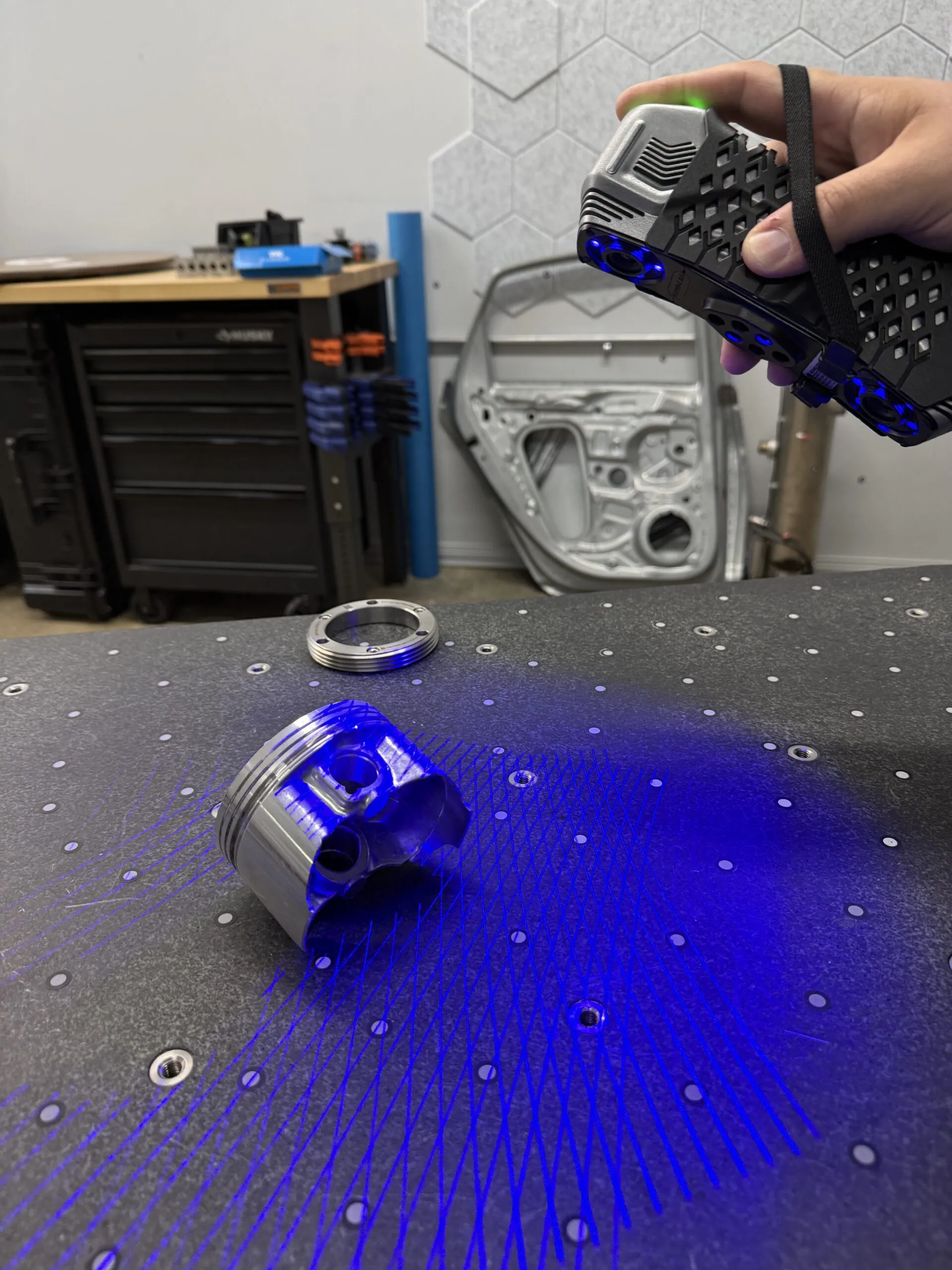
How Does 3D Scanning Work? A Beginner’s Guide to the Technology
You have a part on the bench and no drawing for it. Or you have the drawing, and now you

A first article inspection is where a new part program proves it can actually make the drawing. For aerospace and defense suppliers, the FAI is also the document that survives the audit. Moving first article inspection 3D scanning into your quality workflow lets you verify hundreds of features against the model in a single capture, with full-surface evidence instead of a handful of probed points. This guide walks through a practical, AS9102-ready scan-based FAI process step by step.
We will cover what AS9102 actually requires, how scan data satisfies those requirements, the alignment decision that makes or breaks your deviation results, how to read and present color heat maps, how to verify GD&T callouts in software, and what a clean FAI report package looks like. We will also be honest about where scanning falls short and where a CMM still has to back you up.
First article inspection is the formal, documented verification that a production process produces parts conforming to every drawing requirement. It is performed on a representative part from the first production run (or after a significant change), and it checks 100% of the design characteristics: every dimension, tolerance, note, material spec, and GD&T callout on the drawing. The FAI is not a sampling exercise. It is the proof that the tooling, fixturing, program, and operator instructions are all correct before you commit to volume.
In aerospace and defense, the FAI carries weight far beyond the shop floor. It is a contractual deliverable, an auditable record, and the baseline your customer’s source inspection and your own internal quality system reference for the life of the part number. A weak or incomplete FAI is a finding waiting to happen. A re-run because a design change, a process change, a lapse of two years, or a change of manufacturing location triggered the requirement is common, so the workflow you build needs to be repeatable, not heroic. That is precisely where a scan-based approach earns its keep: the data capture is fast, the evidence is complete, and the report regenerates against a revised model without re-measuring the world by hand.
The governing standard is AS9102, the SAE/IAQG specification for aerospace first article inspection. It does not tell you which gauge or scanner to use. It tells you what has to be documented and how it has to be traceable. AS9102 is built around three forms, and any compliant report has to populate all three:
The two requirements that a scan workflow has to respect are characteristic ballooning (also called bubbling) and measurement traceability. Every feature on the drawing must map to a numbered characteristic on Form 3, and every measured result must trace to a calibrated instrument with a known uncertainty. AS9102 is method-agnostic: it does not care whether a value came from a height gauge, a CMM, or a structured-light scanner, as long as the instrument is qualified for the tolerance and the result is documented. That neutrality is what makes scan-based FAI fully compliant: you are changing the data-acquisition method, not the reporting obligation. Good inspection software closes the loop by exporting Form 3 directly from the ballooned characteristics, so the numbers on the report are the numbers the software computed, with no manual transcription to introduce error.
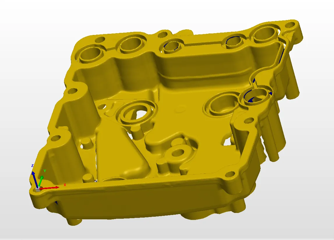
Traditional FAI leans on hand tools, hard gauges, and a CMM running a touch-probe program. It works, and for a part with a dozen simple features it can be the fastest path. But on a complex machined or cast part with hundreds of characteristics (freeform surfaces, thin walls, deep pockets, lots of GD&T), point-by-point probing becomes the bottleneck. Programming the CMM, indicating the part, and touching every feature can consume hours, and you still only have the points you chose to take. Anything between those points is unverified.
Scan-based FAI inverts that. A structured-light or laser scanner captures the entire surface as millions of points in minutes, so you are no longer choosing which features to measure. You have all of them. The same dataset feeds every characteristic on Form 3, drives full-surface deviation heat maps, and supports re-inspection against a new revision without recapturing the part. The trade-off is real and worth stating plainly:
FactorTraditional (CMM + hand tools)Scan-based FAI
Data capturedDiscrete probed points onlyFull-surface point cloud (millions of points)
Capture time, complex partHours of programming + probingMinutes of scanning
CoverageOnly the features you probedEvery visible surface and feature
Freeform / cosmetic surfacesHard to verify between pointsColor heat map across the whole surface
Best single-point accuracySub-micron to low-micronTypically ~25–30 microns, system-dependent
Re-inspection on rev changeRe-probe the partRe-align archived scan to new CAD
The honest summary: a CMM still wins on single-point accuracy for tight bores, gauge-pin features, and datum targets where you need the lowest possible uncertainty. Scanning wins on speed, coverage, and freeform verification, and it is often 50% or more faster end-to-end on parts with high characteristic counts. Most mature aerospace quality groups run both: scanning for the bulk of the report, CMM as the backstop for the handful of features that demand it. Our metrology and 3D inspection services are built around exactly that hybrid model.
The workflow below assumes you are inspecting against a controlled CAD model with a drawing that carries the dimensions and GD&T. The toolchain we reference is Geomagic Control X, which is purpose-built for this kind of CAD-based, traceable inspection. Each step builds the evidence that lands on Form 3.
Start by choosing a scanner matched to the part’s size and tolerance. Small, high-precision parts call for a high-resolution unit like the Artec Spider II; larger or in-cell parts are better suited to a tracked system or a portable arm such as the Scanology AccuArm. If you are evaluating hardware, our portable and handheld 3D scanner lineup covers most FAI use cases. Fixture the part so it is stable and accessible from every angle you need, and avoid clamping in a way that distorts a thin-walled or compliant part.
Prepare the surface. Shiny, dark, or translucent surfaces scatter the projected pattern and produce noisy or missing data, so apply a uniform matting agent. A vanishing scanning spray such as AESUB Blue gives a thin, even coat that sublimates away on its own, leaving no residue to clean off a finished aerospace part. Scan with enough overlap to register cleanly, capture all datum surfaces fully, then clean the mesh: remove outliers and stray points, fill only non-critical holes, and never let smoothing wash out a real feature you intend to measure.
Alignment establishes the coordinate frame in which every deviation is measured, so it is the single most consequential decision in the workflow. Get it wrong and every downstream number is wrong in the same direction. In Control X you import the nominal CAD, then register the scan to it. For an FAI you almost always want a datum (RPS) alignment that reproduces the drawing’s datum reference frame, not a best-fit. We cover the trade-off in detail in the dedicated section below, but the rule of thumb is simple: the part has to be measured in the same frame the designer toleranced it in.
Lock the alignment, confirm the scan is seated correctly on the primary, secondary, and tertiary datums, and save it as the reference alignment for the report. Everything that follows (heat maps, dimensional callouts, GD&T evaluation) inherits this frame.
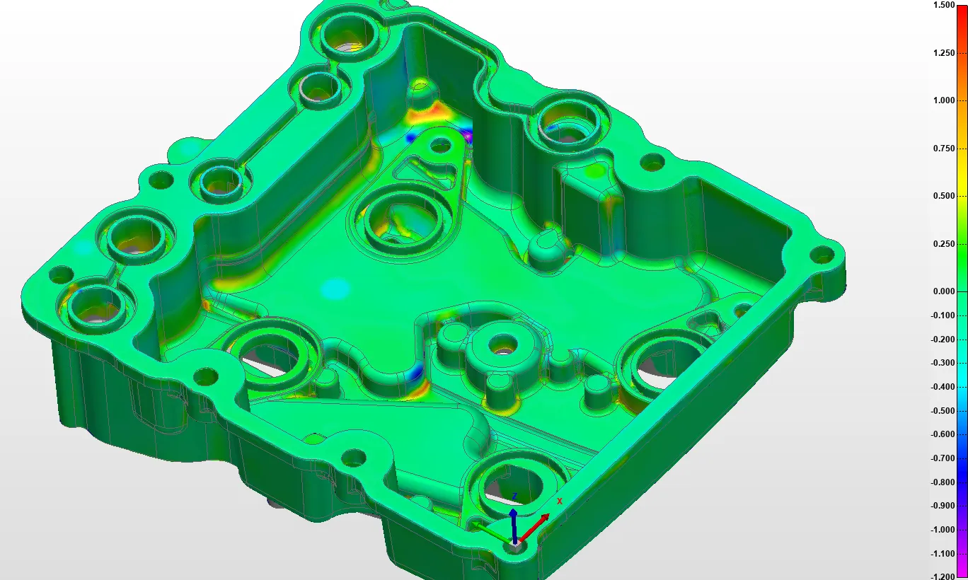
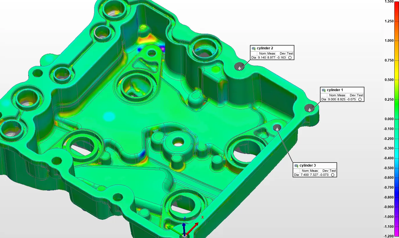
With the scan aligned, compute a surface comparison. The software calculates the signed distance from every scan point to the nearest CAD surface and renders it as a color deviation heat map, a whole-surface error map where green is on-nominal, warm colors (yellow/red) show material high, and cool colors (blue) show material low. This is the diagnostic that traditional FAI simply cannot produce: instead of inferring from a few points, you see the actual form of the part, including warpage, springback, sink, and machining bias that only reveal themselves across the full surface.
Set the color scale deliberately. A tolerance band tied to the drawing (for example ±0.005 in / ±0.13 mm) makes pass/fail obvious at a glance: anything outside the green band is out of tolerance. Drop annotation labels at the worst hot spots so the report reader sees the actual deviation value, not just a color. The heat map is not a Form 3 characteristic by itself, but it is powerful supporting evidence and it is usually the first thing a customer’s quality engineer looks at.
Dimensional points and heat maps cover size and form, but the drawing’s GD&T controls (position, profile, flatness, perpendicularity, concentricity, runout) have to be evaluated as feature-control frames, not as raw deviations. Control X reads geometric tolerances and computes them properly: it fits the actual features, applies the datum reference frame, accounts for material condition modifiers (MMC/LMF), and reports the calculated tolerance against the allowed value. Profile of a surface, for instance, is evaluated as a zone around the nominal surface in the datum frame, exactly how the inspector at your customer would interpret it.
This is where a team’s understanding of the standard matters as much as the software. If your engineers are shaky on how a position tolerance shifts under MMC, or which datum precedence the frame implies, the software will still output a number, but no one will be able to defend it in an audit. Solid GD&T training is the difference between checking a box and actually verifying conformance. Balloon every GD&T callout, evaluate it in software, and tie each result back to its numbered characteristic on Form 3.
The final step is producing the AS9102 package. With characteristics ballooned and evaluated, Control X exports a Form 3 populated directly from the measured results (characteristic number, requirement, tolerance, actual, and pass/fail) alongside the supporting heat maps and GD&T evaluations. A clean scan-based FAI report typically includes:
Because the report regenerates from the saved alignment and the model, a revision change or a delta FAI does not mean starting over. You re-align the archived scan to the new CAD and re-export.
This is the most misunderstood decision in scan-based FAI, and getting it wrong is the most common way an otherwise good inspection produces misleading results. The two methods answer different questions.
Best-fit alignment mathematically minimizes the overall deviation between the scan and the CAD: it floats the part into the position of least total error. That is the right choice when you want to characterize form on a freeform or cosmetic surface, or during reverse engineering and process development where there is no datum scheme yet. It flatters the part: it spreads error evenly and makes the heat map look as good as the geometry allows.
Datum alignment (often implemented as RPS, reference point system) constrains the part to the drawing’s datum reference frame (primary, secondary, tertiary) exactly as the designer defined function and exactly as a CMM program or a hard fixture would. This is the correct method for FAI, because GD&T callouts are meaningless outside their datum frame. A position tolerance, a profile relative to A-B-C, a perpendicularity: all of them only have an answer once the part is seated on its datums.
QuestionBest-fitDatum / RPS
Use it forForm/profile study, reverse engineering, no datumsFAI, GD&T conformance, functional verification
What it minimizesTotal deviation across the whole surfaceNothing; it seats the part on its datums
GD&T validityNot valid for datum-referenced tolerancesRequired for datum-referenced tolerances
Heat map appearanceOptimistically evenHonest; shows true bias from datums
The practical takeaway: use datum alignment for the FAI of record. A best-fit heat map can be a useful secondary view to understand a part’s form, but never report GD&T results off a best-fit. If your datum features are themselves out of tolerance, the alignment will reveal it. That is a feature of the method, not a problem with it.
Most scan-based FAI failures are process failures, not technology failures. The same handful of mistakes show up across new adopters:
The cure for most of these is procedure plus training. A written work instruction that fixes the surface prep, the alignment scheme, and the report template removes the guesswork, and GD&T fundamentals training ensures the engineer reading the feature-control frames knows what the software is actually computing. If you would rather not stand up the capability in-house at all, our 3D scanning services deliver inspection-ready data and reports.
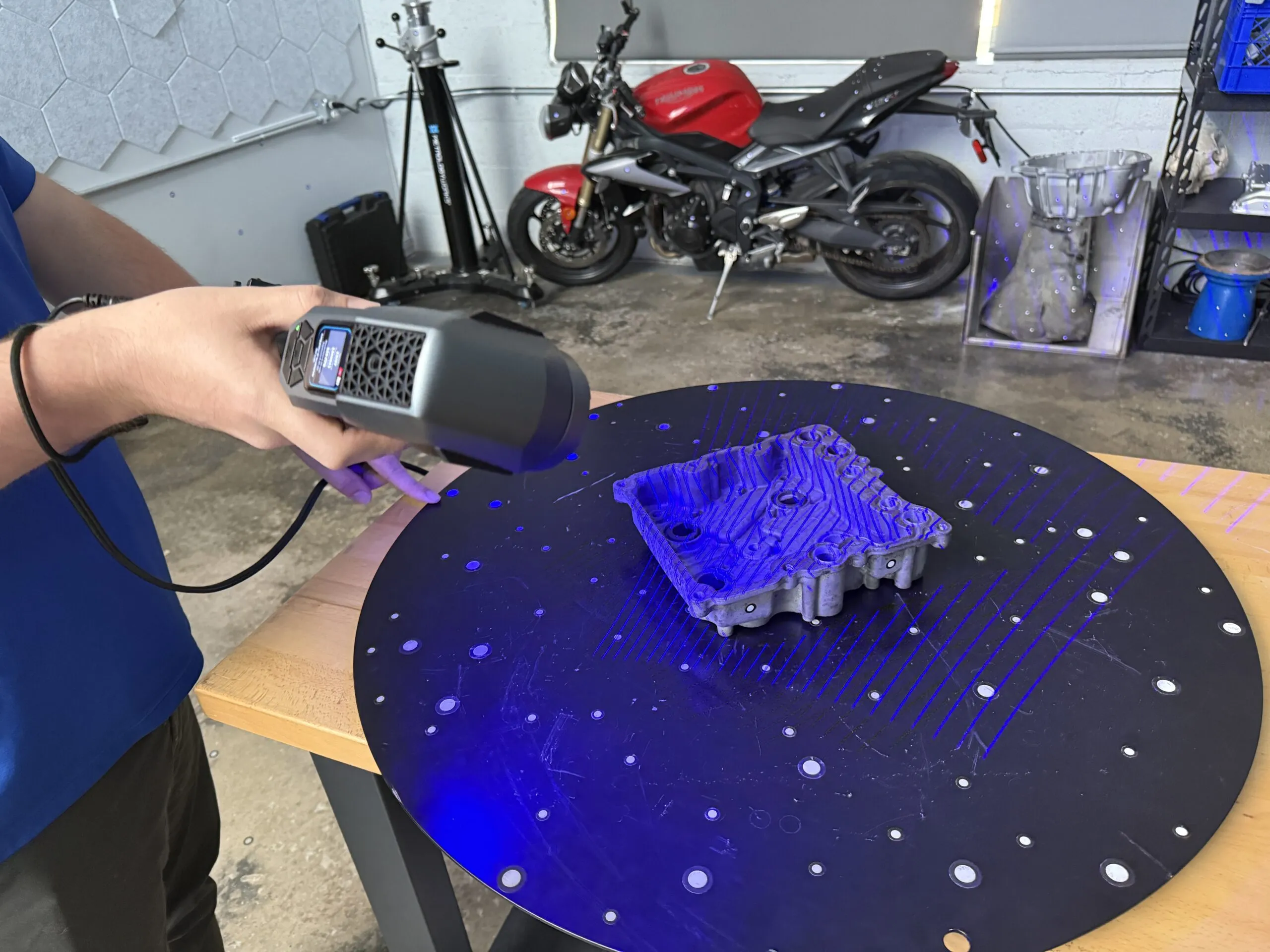
An honest workflow acknowledges its limits. Optical scanning has line-of-sight and resolution constraints, and there are features where a touch probe is simply the better instrument. Deep, narrow bores and blind holes can be hard or impossible to fully capture optically, because the scanner cannot see down a small-diameter hole. Internal threads, sharp edges, and razor-thin features push the resolution and edge-fidelity of any scanner. And for the very tightest tolerances (gauge-pin bores, bearing journals, datum targets toleranced in the single-digit microns), a scanner’s typical ~25–30 micron uncertainty may not leave enough margin against the tolerance band.
The answer is not to choose one tool. It is to build a hybrid FAI: scan to verify the bulk of the characteristics and the full-surface form quickly, then use a CMM or a portable arm as the backstop on the handful of features that demand the lowest uncertainty or that the scanner cannot reach. A portable CMM such as the Scanology AccuArm brings hard-probe accuracy to those features without leaving the inspection cell. Each method’s results land on the same Form 3, each with its own documented instrument and uncertainty, which is exactly what AS9102 expects. The standard never asked you to use one tool; it asked you to verify every characteristic with a qualified method and document it.
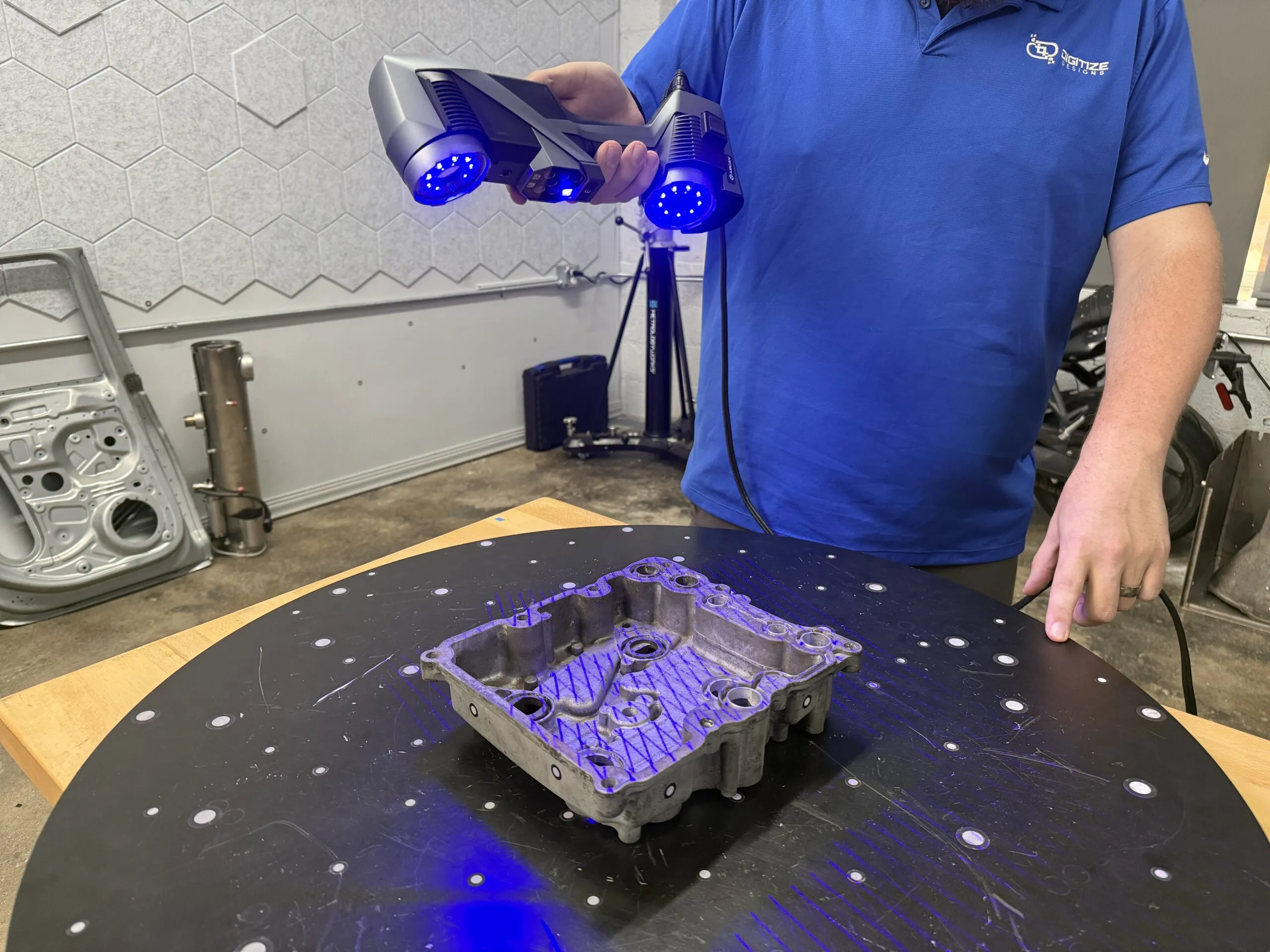
Building a repeatable, audit-ready scan-based FAI workflow is equal parts the right hardware, the right software, and the people who understand the standard behind it. We help aerospace and defense suppliers put all three in place: selecting a scanner matched to your tolerances, standing up Geomagic Control X for traceable, AS9102-ready inspection, and training your team through GD&T Basics Training so the GD&T results you report are results you can defend. When you would rather hand off the work, our engineers deliver complete inspection packages through our metrology and 3D inspection services.
Whether you are replacing a slow CMM-only process, building a first-time FAI capability, or just want a second set of expert eyes on your alignment strategy, our team can help you scope the right toolchain. Contact us for a consultation or a quote, and we will help you build an FAI workflow that holds up to the audit.
You have a part on the bench and no drawing for it. Or you have the drawing, and now you
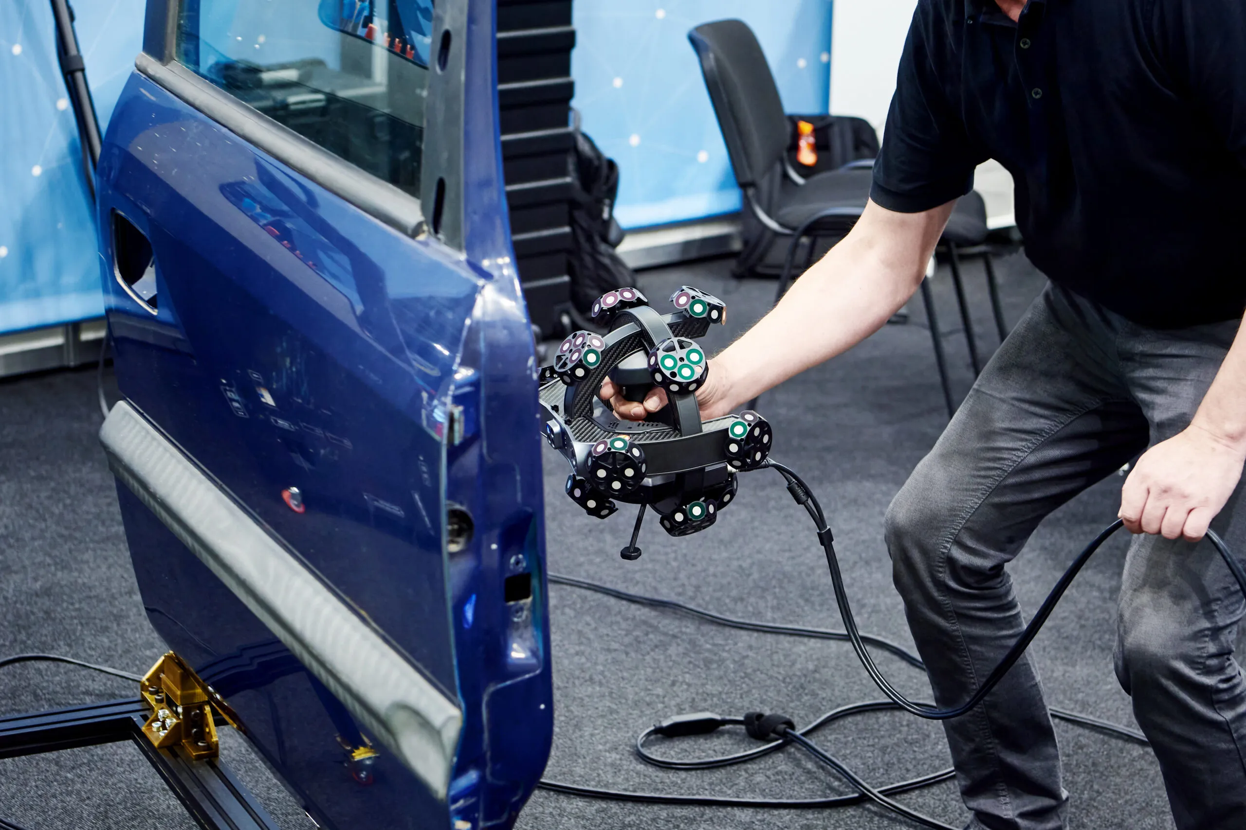
A fender comes off the press and something is off. The hole pattern checks out on the CMM and every

For most of the twentieth century, a crime scene was preserved with a tape measure, a roll of film, and
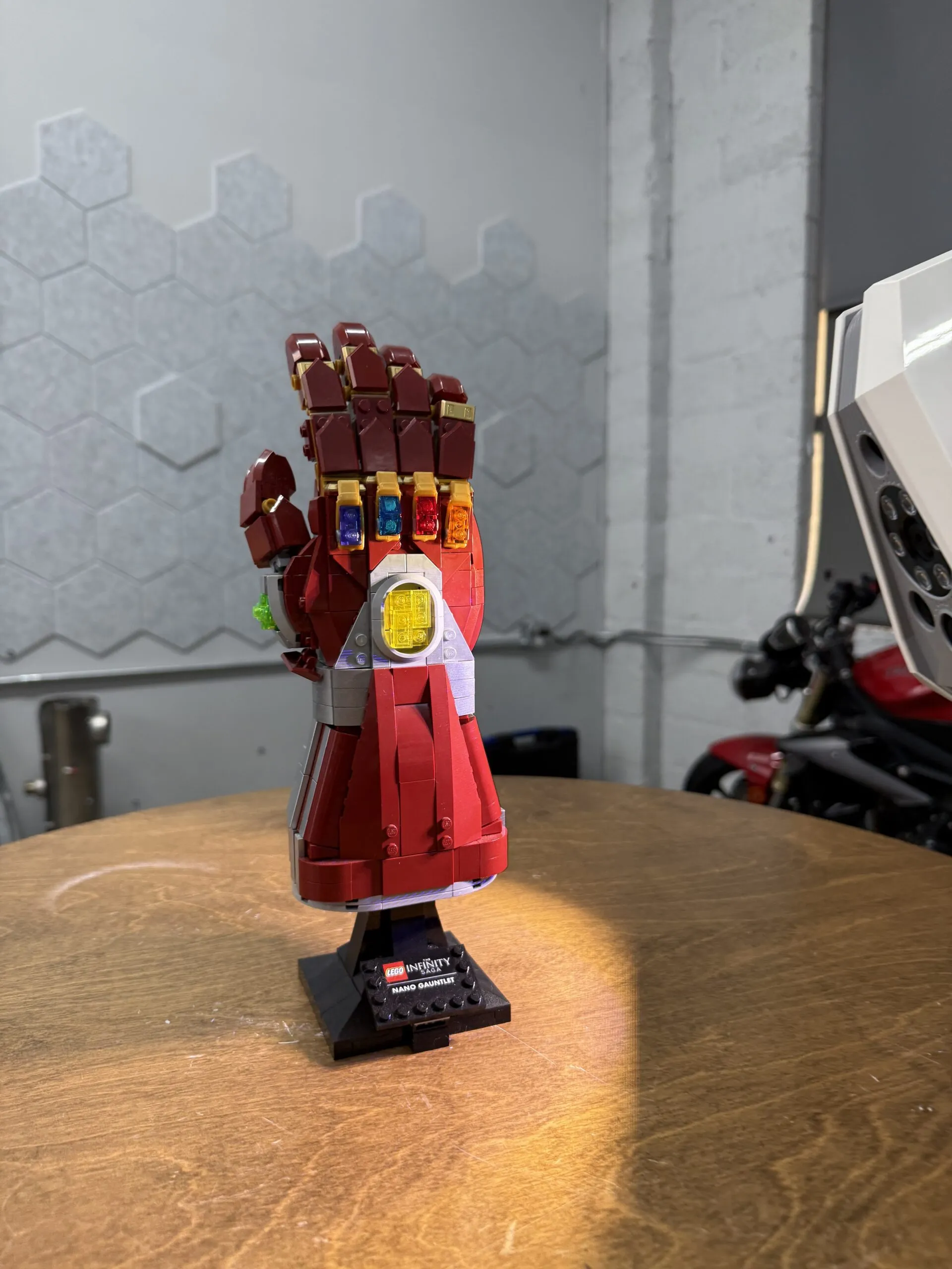
If you have ever searched for a way to turn a physical object into a digital model, you have probably