Long-Distance 3D Scanning for Infrastructure
Huge infrastructure projects present unique challenges that can only be addressed with advanced solutions like long-range 3D scanners. Whether it’s
There’s a version of problem-solving that looks like progress: a windshield held in place with over an inch of rubber filler, a part that technically fits, until it doesn’t, a workaround that becomes permanent because no one goes back to ask why the gap existed in the first place.
That’s not engineering. That’s deferred cost. And the root cause is almost always the same: engineering tolerance was never properly defined, because the real-world geometry was never properly measured.
When real-world geometry is wrong, everything built on top of it is wrong. Edge clearances that don’t match the actual opening. Corners that can’t hold a consistent radius. Surfaces that won’t align no matter how well the part was made. These aren’t manufacturing failures — they’re data failures.
Standard specs assume ideal conditions. Real-world geometry doesn’t cooperate. A nominal dimension from a drawing doesn’t account for frame flex, installation wear, or the cumulative variation that shows up in every physical object that’s been in service. Defining engineering tolerance from unmeasured assumptions means designing to a fiction.
3D scanning changes the equation entirely. Instead of designing to a standard spec and hoping it fits, you design to the actual opening — the real-world geometry of every surface, edge, and corner relationship as it physically exists.
The scan captures every dimension relevant to engineering tolerance: exact edge clearances, true corner radii, and surface relationships across the full part envelope. That data becomes the design foundation. The result is a part designed to fit, not forced to.
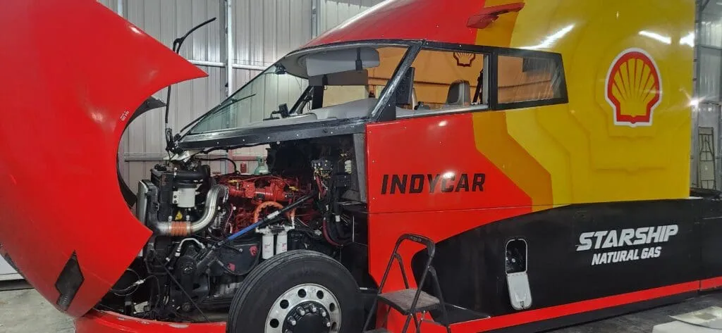
For one custom windshield project, this meant delivering exact edge clearances, clean radii on all four corners, and manufacturing-ready drawings the glassmaker could use immediately — before a single piece of glass was cut. No trial fits. No adjustment iterations. No filler.
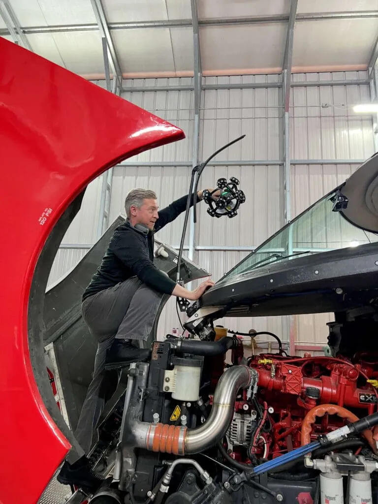
Precision at this level requires the right equipment. The SCANOLOGY TrackScan Sharp-S captures 99 simultaneous laser lines and 4.86 million measurements per second, fully wireless, with a 135 m³ measurement range. It’s the same industrial-grade technology used in aerospace and heavy industry, where engineering tolerance isn’t optional.
Speed matters less than accuracy that holds up at manufacturing. Fast scanning that produces bad data just fails faster. The value of a system like this is that the data goes straight from scan to drawing to production, without second-guessing what’s in between.
Legacy parts fail. Custom applications demand engineering tolerance that standard components simply can’t deliver. And every time someone reaches for filler instead of facts, the problem compounds, never shrinks.
Reverse engineering done right doesn’t start with assumptions. It starts with the real-world geometry that’s actually there and derives the engineering tolerance the application demands from it. That’s not a niche capability, it’s the baseline for any solution worth having.
We turn real-world geometry into exact solutions, with the engineering tolerance your application actually demands. If a past solution is starting to show its cracks, we’ll start where the answer always is: the data.
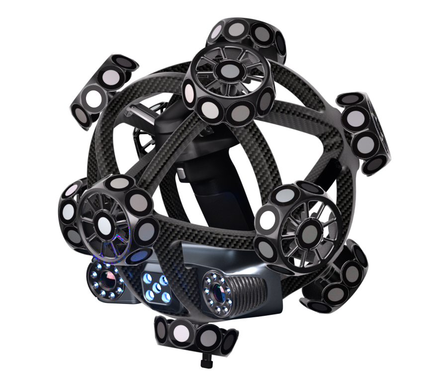
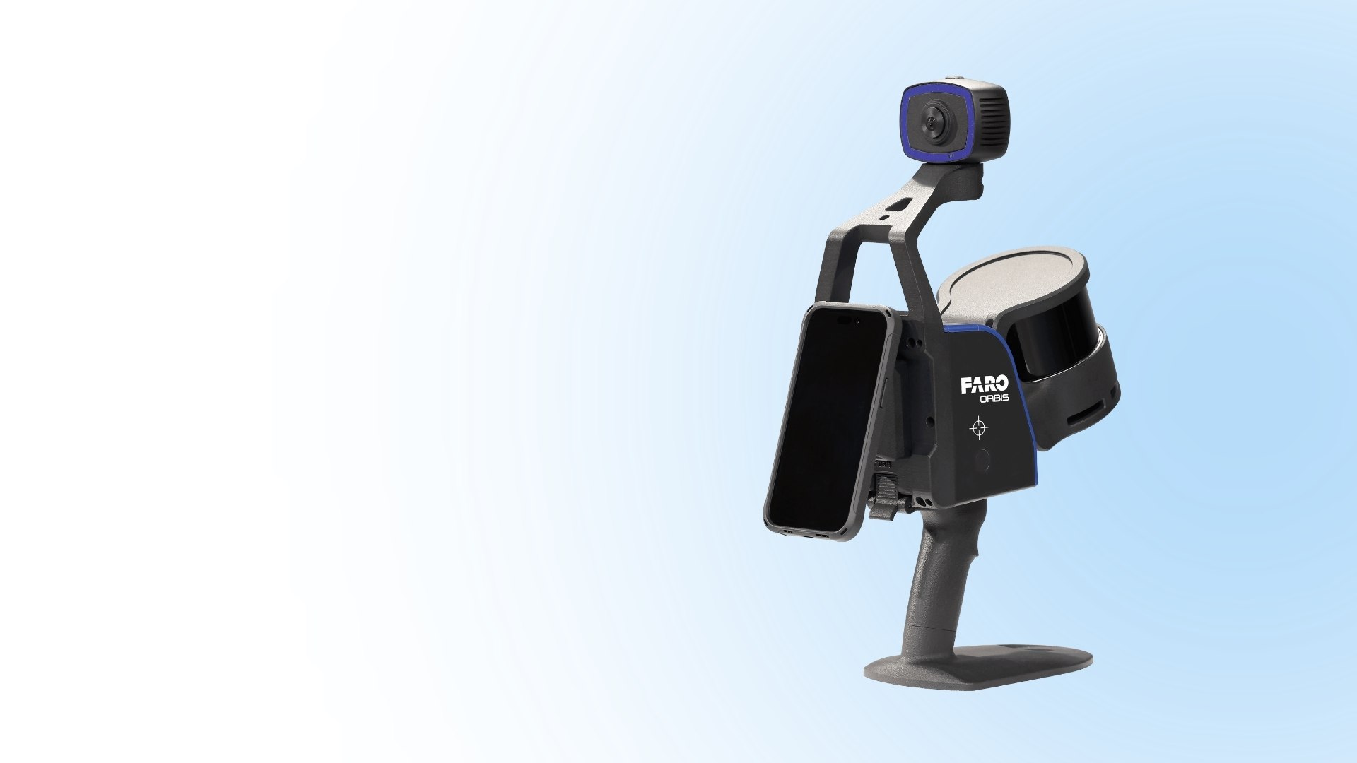
Versatile 3D measurement system combining portable scanner and optical tracker for accurate capture.
Huge infrastructure projects present unique challenges that can only be addressed with advanced solutions like long-range 3D scanners. Whether it’s
Different long-range scanner brands offer varying features and capabilities; hence the need to understand the most crucial aspects of long-range
The key difference between long-range and short-range scanners is the maximum distance at which they can capture data. Ordinarily, long-range

The key elements to consider in long-range 3D scanners include accuracy, scan speed, resolution, scanning mechanism, and ease of use.